Conveying device for industrial electrical automatic production

A technology for electrical automation, conveying devices, used in cleaning devices, transportation and packaging, conveyors, etc.

Pending Publication Date: 2021-09-07
徐炜镕
View PDF10 Cites 0 Cited by
  • Summary
  • Abstract
  • Description
  • Claims
  • Application Information

AI Technical Summary

Problems solved by technology

[0004] The purpose of the present invention is to provide a transmission device for industrial electri...

Method used


Image

  • Conveying device for industrial electrical automatic production
  • Conveying device for industrial electrical automatic production
  • Conveying device for industrial electrical automatic production

Examples


Embodiment 1

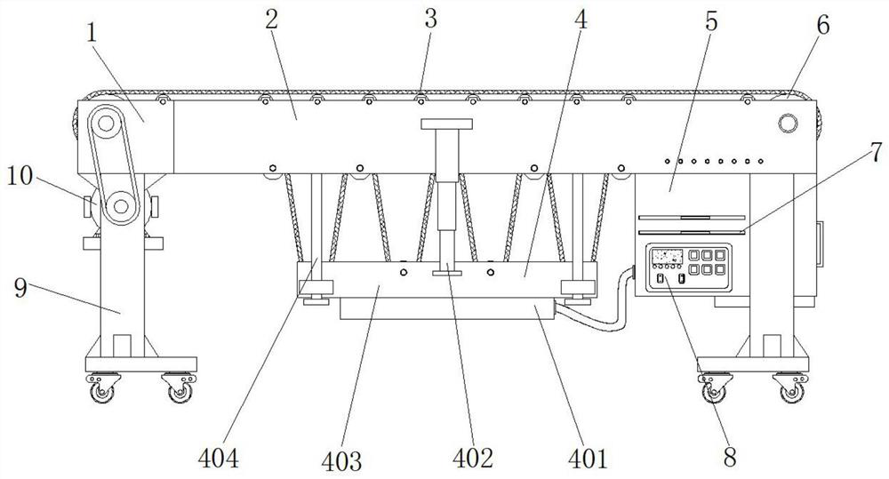
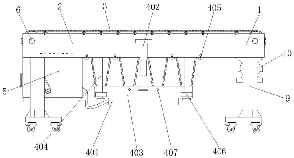
[0040] Example 1, such as Figure 1-7 As shown, when it is necessary to adjust the transmission distance of the installation device, the servo motor 114 can be controlled to drive the threaded rod 111 to rotate, and due to the action of the thread, the moving plate 113 is forced to drive the limit slide bar 112 and the end of the installation seat 1 away from the installation frame 2 move, and the limit slide bar 112 gradually protrudes from the inside of the limit chute 116, and the universal wheel at the bottom of the support column 9 rolls on the ground. In the process, the two groups of electric lifting rods 402 are gradually shortened, so that the first guide The distance between the roller 405 and the second guide roller 407 is gradually shortened, and a length of conveyor belt 3 is released to match the distance between the mounting seat 1 and the mounting frame 2. The driving assembly 10 drives the main guide roller 6 and the conveyor belt 3 to rotate to carry out the ...

Embodiment 2

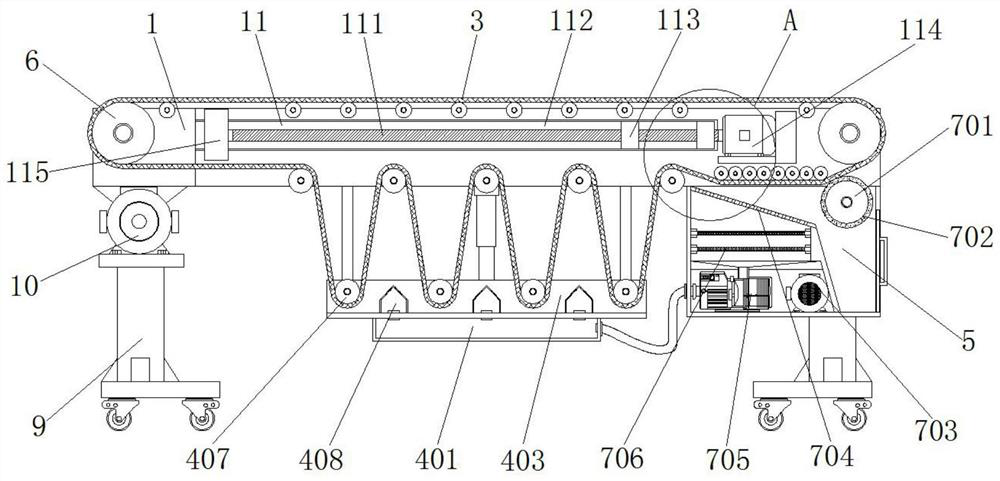
[0041] Example 2, such as Figure 1-9 As shown, if the device transports industrial dust materials, some of the dust materials will adhere to the outside of the conveyor belt 3. During the process of conveying materials by the device, the control panel 8 controls the second drive assembly 703 to drive the third guide roller. 701 rotates, use the brush 702 on the outside of the third guide roller 701 to clean the outside of the conveyor belt 3, and the material dust that is cleaned is sucked into the inside of the filter chamber 707 by the air pump 705, and filtered by two sets of filter screens 706 It is discharged from the output end of the air pump 705, and the larger dust pieces attached to the outside of the conveyor belt 3 are brushed by the brush 702 and rolled down to the inner bottom of the installation chamber 5, thereby preventing industrial materials from adhering to the outside of the conveyor belt 3 for a long time. 3 cause corrosion, regularly open the door of th...


PUM


Abstract

The invention discloses a conveying device for industrial electrical automatic production. The device comprises two sets of mounting bases and two sets of mounting frames, supporting columns are symmetrically mounted at the ends, away from each other, of the bottoms of the two sets of mounting bases and mounting frames, main guide rollers are symmetrically arranged at the ends, away from each other, of the inner sides of the two sets of mounting bases and the two sets of mounting frames, a conveying belt is jointly arranged on the outer sides of the two sets of main guide rollers, and a first driving assembly in transmission connection with the adjacent main guide roller is arranged at the bottom of one mounting base. Through cooperative use of the mounting bases, the mounting frames, the conveying belt, an adjusting assembly, the first driving assembly and an extension assembly, the distance between the first guide roller and the second guide roller is shortened, a certain length of the conveying belt is released to cooperate with the mutual separation of the mounting bases and the mounting frames, the conveying distance of the whole conveying device is automatically adjusted, and therefore, the application range and the use effect of the device are greatly improved.

Description

technical field [0001] The invention relates to the technical field of industrial production transmission devices, in particular to a transmission device for industrial electrical automation production. Background technique [0002] In the middle of the 17th century, the United States began to use aerial cableways to convey bulk materials; in the middle of the 19th century, industrial production transmission devices of various modern structures appeared one after another. Screw conveyors; in 1905, steel belt conveyors appeared in Switzerland; in 1906, inertial conveyors appeared in the United Kingdom and Germany. Since then, industrial production transmission devices have been affected by technological advancements in machinery manufacturing, electrical machinery, chemical and metallurgical industries , Continuous improvement, and gradually develop from the completion of the transmission inside the workshop to the completion of material handling within the enterprise, betwee...

Claims


Application Information

Patent Timeline
IPC IPC(8): B65G21/14B65G45/18B65G45/26
CPCB65G21/14B65G45/18B65G45/26
Inventor 徐炜镕
Owner 徐炜镕
Why Eureka
Try Eureka