Diagonal bracing device and installation structure for construction of bridge pylons and columns

A technology for installing structures and bridge pylons, which is applied to bridges, bridge construction, bridge parts, etc., can solve the problems of heavy workload, low work efficiency, and high cost, and achieve good construction quality of bridge pylons, low time cost, and economic benefits Good results

Active Publication Date: 2022-04-01
GUANGXI UNIV +2
View PDF2 Cites 0 Cited by
  • Summary
  • Abstract
  • Description
  • Claims
  • Application Information

AI Technical Summary

Problems solved by technology

[0003] There are three traditional methods for controlling the stress of bridge tower columns: one is the full house support method, which has a large workload, low work efficiency and greater danger; the other is to set horizontal horizontal braces. Although this method reduces the workload, However, it cannot overcome the deformation and lateral displacement of the bridge tower column due to its own weight; the third is to use jacks to change the passive support in method 2 into active support. Although this method improves the shortcomings of the above two methods, the horizontal brace structure The horizontal bracing is relatively long, and the efficiency of horizontal bracing is low. In order to ensure the stability of the force, a large cross-section is adopted, resulting in a large weight. Therefore, the existing horizontal cross bracing is difficult, expensive, time-consuming and poor in reliability.
Especially when the bridge tower column is high and the slope is large, it is necessary to set up multiple horizontal horizontal braces or combine the above-mentioned solutions, and the disadvantages of the existing technology and equipment are becoming more and more prominent.

Method used


Image

  • Diagonal bracing device and installation structure for construction of bridge pylons and columns
  • Diagonal bracing device and installation structure for construction of bridge pylons and columns
  • Diagonal bracing device and installation structure for construction of bridge pylons and columns

Examples


Embodiment 1

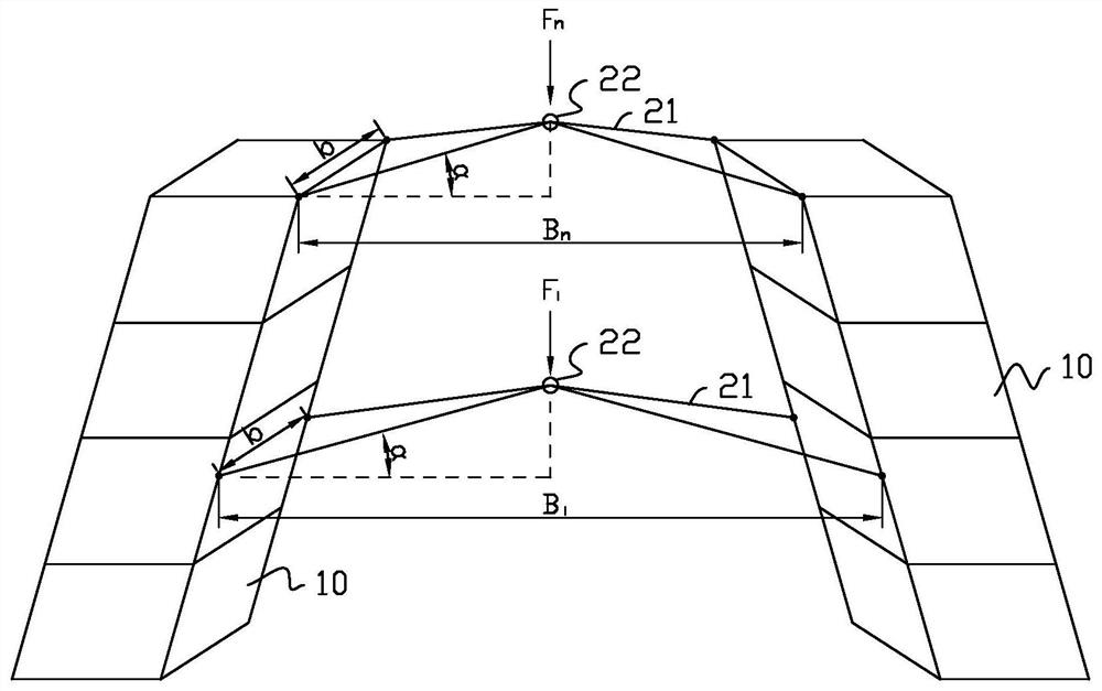
[0053] Embodiment one: tension force F=200kN, bridge pylon column are subjected to the height h=28m of horizontal transverse force, change α angle (from small to large), calculate the lateral stress σ of f transverse and bridge pylon column root, And verify that the structure is safe.

[0054] Table 2

[0055]

[0056] It can be seen from Table 2 that when F and h are constant, the smaller the α angle, the f 横向 The larger the , the stress σ generated by the self-weight of the pylon column 10 can be effectively offset. From the data in Table 2, it can be seen that when the α angle is within 45°, the stress σ of the concrete outside the 10 roots of the bridge tower column does not exceed 1MPa; when the α angle is less than 1°, the σ 钢筋 It is 201.377MPa, which exceeds the yield stress of the steel bar ([σ]=145MPa), so the α angle should not be less than 1°. To sum up, the value range of α angle should be 2°-45°.

Embodiment 2

[0057] Embodiment two: tension force F=400kN is set, the height h=28m of bridge pylon column 10 being subjected to horizontal transverse force, changes α angle (from small to large), calculates and obtains f 横向 and the external stress σ at the root of the bridge tower column 10, and verify whether the structure is safe.

[0058] table 3

[0059]

[0060] It can be seen from Table 3 that when F and h are constant, the smaller the α angle is, the larger the lateral f of the diagonal bracing member 21 will be, which can effectively offset the stress σ generated by the self-weight of the pylon column 10. From the data in Table 2, it can be seen that when the α angle is within 45°, the stress σ of the concrete outside the 10 roots of the bridge tower column does not exceed 1MPa; when the α angle is less than 1°, the σ 钢筋 It is 201.377MPa, which exceeds the yield stress of the steel bar ([σ]=145MPa), so the α angle should not be less than 1°. To sum up, the value range of α ang...

Embodiment 3

[0061] Embodiment three: tension force F=200kN is set, the height h=32m of bridge pylon column 10 being subjected to horizontal transverse force, changes α angle (from small to large), calculates and obtains f 横向 and the stress σ outside the root of the pylon column, and verify whether the structure is safe.

[0062] Table 4

[0063]

[0064] It can be seen from Table 4 that when F and h are constant, the smaller the α angle, the larger the lateral f of the diagonal bracing member 21, which can effectively offset the stress σ generated by the self-weight of the pylon column 10. From the data in Table 2, it can be seen that when the α angle is 40°, the stress σ of the concrete outside the 10 roots of the pylon column exceeds 1 MPa; when the α angle is less than 1°, the σ 钢筋 It is 197.618MPa, which exceeds the yield stress of the steel bar ([σ]=145MPa), so the α angle should not be less than 1°. To sum up, the value range of α angle should be 2°-35°.

[0065] Combining Tab...


PUM


Abstract

The invention relates to the field of bridge tower construction, and discloses a diagonal brace device and an installation structure for bridge tower column construction, including making the diagonal brace device, gradually constructing the bridge tower column and installing the diagonal brace device on two bridges during the construction process. Between the pylons, tension is finally applied to the diagonal bracing device so that the cross bridge supports the two pylons. The present invention adopts the form of multiple triangular pyramid diagonal braces, and applies downward vertical force on the top of the diagonal braces, so as to decompose the horizontal thrust of multiple transverse bridges and act on the bridge tower column, thereby reducing the self-weight and construction load. Tensile strain on the outer side of the bottom of the bridge tower column and the outer side of the bridge tower column at the first diagonal brace. The method of applying vertical force by the diagonal bracing device is relatively simple, the internal force is adjustable and the efficiency is high; under the same support effect requirements, the diagonal bracing device can significantly reduce the number of temporary horizontal braces, and the cross section of the diagonal bracing member is more horizontal than the traditional multi-layer The cross brace has the advantages of small cross-section, light weight, and convenient construction, and has significant engineering significance and economic and social benefits.

Description

technical field [0001] The invention belongs to the field of bridge construction, and in particular relates to a diagonal bracing device and an installation structure for bridge tower and column construction. Background technique [0002] Most of the towers, towers, and cross bridges are designed as inclined structures, the purpose of which is to express the personality and visual effects of the towering bridge towers. The overall shape of the bridge reflects the architect's pursuit of aesthetics and cultural expression. More importantly, the design of the bridge tower column must be suitable for the arrangement of the stay cable or the main cable, the force transmission should be simple and clear, and under the action of the dead load, the bridge tower column should be in the state of axial compression as much as possible. Generally speaking, the layout of the bridge tower column has several types such as single column, A-shaped, inverted Y-shaped and H-shaped. Among them,...

Claims


Application Information

Patent Timeline
Patent Type & Authority Patents(China)
IPC IPC(8): E01D21/00E01D19/14
CPCE01D21/00E01D19/14
Inventor 龙夏毅王龙林杨涛郝天之黄海峰卓小丽
Owner GUANGXI UNIV
Why Eureka
Try Eureka