Fixed-mass cotton fiber sample producer
A cotton fiber and generator technology, applied in the field of cotton fiber sample generators with fixed quality, can solve the problems of long operation time, different operation techniques and proficiency, and high work intensity, so as to improve inspection efficiency, improve manpower difficulties, Avoid the effect of large errors
- Summary
- Abstract
- Description
- Claims
- Application Information
AI Technical Summary
Problems solved by technology
Method used
Image

Examples
Embodiment Construction
[0024] The technical solutions in the embodiments of the present invention will be clearly and completely described below in conjunction with the accompanying drawings in the embodiments of the present invention. Obviously, the described embodiments are only some of the embodiments of the present invention, not all of them. Based on The embodiments of the present invention and all other embodiments obtained by persons of ordinary skill in the art without making creative efforts belong to the protection scope of the present invention.
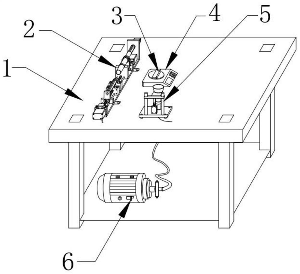
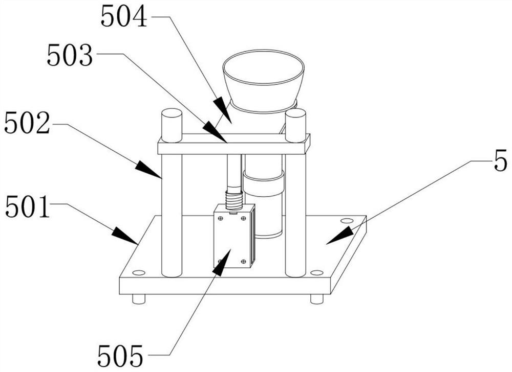
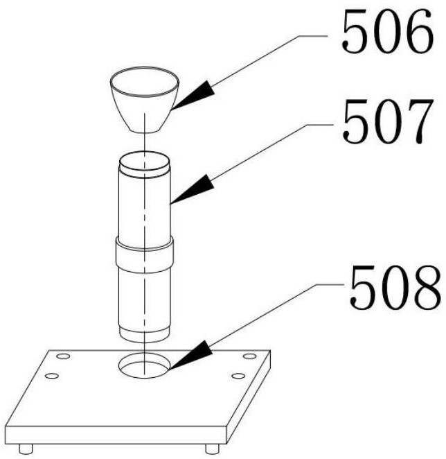
[0025] see Figure 1-3 , the present invention provides a technical solution: a fixed-quality cotton fiber sample generator, including a fixed-quality cotton fiber sample accurate extraction mechanism 2 and a cotton fiber sample storage mechanism 5, the bottom of the cotton fiber sample storage mechanism 5 is provided with a fixed bottom plate 501, the left and right symmetrical slide rails 502 are arranged on the front of the fixed base plate 5...
PUM
 Abstract
Description
Claims
Application Information
PatSnap Eureka turns technology decisions into work you can execute. Powered by our Innovation Knowledge Graph, it runs expert workflows across engineering, life sciences, materials and intellectual property. Get your review-ready output in minutes.


