Heating method for detonation pipeline

A heating method and pipeline technology, applied in ohmic resistance heating parts, instruments, control/regulation systems, etc., can solve the problems of cumbersome, uneven heating, slow heating, etc.

Active Publication Date: 2021-09-07
UNIV OF SCI & TECH OF CHINA
View PDF10 Cites 0 Cited by
  • Summary
  • Abstract
  • Description
  • Claims
  • Application Information

AI Technical Summary

Problems solved by technology

[0003] The invention provides a heating method for detonation pipelines, which uses the combination of electrode heating and electric heating bands to realize rapid, efficient and balanced

Method used


Image

  • Heating method for detonation pipeline
  • Heating method for detonation pipeline
  • Heating method for detonation pipeline

Examples


Embodiment 1

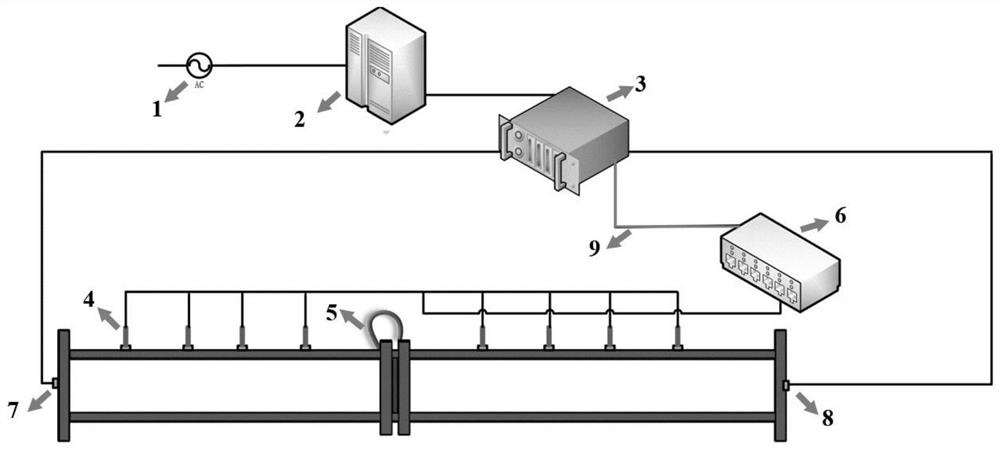
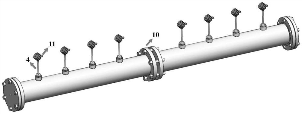
[0027] A detonation tube with a diameter of 48 mm and a length of 4 meters is selected, and 8 thermocouple sensor interfaces are arranged above the tube. refer to figure 1 , After assembling the heating system, inject a certain volume of liquid fuel into the pipeline, set the preset temperature of the temperature measuring and controlling instrument to 100°C, set the output voltage of the constant voltage source to 5V, and turn on the power.

Embodiment 2

[0029] A detonation tube with a diameter of 48 mm and a length of 4 meters was selected. Follow the same steps to assemble the heating system, adjust the preset temperature of the temperature measuring and controlling instrument to 100°C, increase the output voltage of the constant voltage source to 15V, and turn on the power.

Embodiment 3

[0031] A detonation tube with a diameter of 20 mm and a length of 8 m was selected. Set the preset temperature of the temperature measuring and controlling instrument to 100°C, and set the output voltage of the constant voltage source to 15V.

[0032]After the pipelines of the above three embodiments are heated for 60s, the temperature of different channels displayed by the temperature is summarized in Table 1:

[0033]

[0034] Table 1 Unit: °C

[0035] From the data collected in the embodiment of the present invention, it can be seen that the heating uniformity of the heating method for the detonation pipeline is very good, and the temperature difference between different parts of the pipeline is extremely small; It can be heated to the preset temperature by left or right, so that the liquid fuel can be vaporized evenly and quickly.


PUM

PropertyMeasurementUnit
Diameteraaaaaaaaaa
Lengthaaaaaaaaaa
Diameteraaaaaaaaaa

Abstract

The invention discloses a heating method for a detonation pipeline. The heating method is mainly based on electrode discharge heating, and meanwhile, a metal heating belt is configured for heating; and a heating system comprises a temperature acquisition system and a temperature control system. The method has the advantages that the heating rate of the pipeline is greatly increased, the uniformity and safety of pipeline heating are improved, meanwhile, compared with a traditional heating mode, the method is convenient and rapid, and the problem of research limitation caused by limitation of the heating mode in the field of liquid fuel detonation is solved. Heating electrodes are connected to two ends of a detonation pipeline, output low voltage and high current, and are controlled by a step-down transformer connected with a power supply and a constant voltage source; the metal heating belt is positioned on the flange plates connected with the two pipelines and connected with the side surfaces of the two flange plates; the temperature acquisition system comprises a plurality of thermocouple sensors and a temperature measuring and controlling instrument; the thermocouple sensors are connected to a plurality of temperature measuring point interface ends of the pipeline, and the other ends of the thermocouple sensors are connected to a temperature measuring and controlling instrument; and the temperature control system is controlled by the temperature measuring and controlling instrument connected with a constant voltage source.

Description

technical field [0001] The invention belongs to the technical field of heating systems, and in particular relates to a heating method for detonation pipelines. Background technique [0002] The detonation pipeline is an experimental device that achieves a stable detonation velocity (C-J detonation velocity) by igniting a gas-phase combustible mixture for combustion acceleration. It is especially widely used in the field of gas detonation research. In recent years, many scholars at home and abroad have carried out detonation experiments of liquid fuel in detonation pipelines. In order to distribute the liquid fuel evenly in the pipeline space and fully mix it with the oxidant, it is necessary to indirectly heat the pipeline to vaporize the fuel in the pipeline to a homogeneous gas phase state. In this process, the uniformity and safety of pipeline heating are particularly important. Most of the traditional pipeline heating methods are metal heating belt heating method, and ...

Claims


Application Information

Patent Timeline
IPC IPC(8): G05D23/22H05B3/02
CPCG05D23/22H05B3/02
Inventor 王鲁庆陈蝶马宏昊刘锐李停纪田
Owner UNIV OF SCI & TECH OF CHINA
Why Eureka
Try Eureka