Panoramic video minimum deformation degree mapping method

A technology of panoramic video and mapping method, applied in the field of panoramic video coding, which can solve the problems of compression coding burden, affecting subjective and objective quality evaluation, uneven sampling density, etc.

Inactive Publication Date: 2021-09-07
SHANGHAI UNIV +1
View PDF6 Cites 0 Cited by
  • Summary
  • Abstract
  • Description
  • Claims
  • Application Information

AI Technical Summary

Problems solved by technology

Hexahedral mapping improves the problem of uneven sampling density, but there is still obvious uneven sampling density
Octagonal mapping is to map a spherical surface into an octagonal shape based on a specific sampling formula, and reorganize a compact rectangular video by cutting and rearranging the pixels. However, this method further improves the problem of uneven

Method used


Image

  • Panoramic video minimum deformation degree mapping method
  • Panoramic video minimum deformation degree mapping method
  • Panoramic video minimum deformation degree mapping method

Examples


Embodiment 1

[0089] In this embodiment, the panoramic video minimum distortion mapping method is used to process a frame of image in the latitude and longitude format with a resolution of 8192×4096 in the panoramic video, and the panoramic video is a color video with three components. Assuming that the color components used are RGB, RGB is still used to represent the color of each sampling point after sampling, assuming that the requirements for spatial resolution are the same for the three components, all of which are W=4928, N=1792, and the quantization accuracy requirements are Each component is also the same, quantized to 256 levels. Then for each component, repeat the following steps S1-S4:

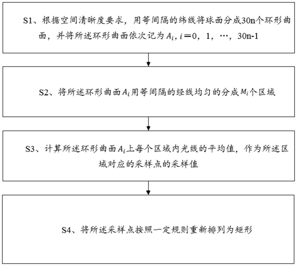
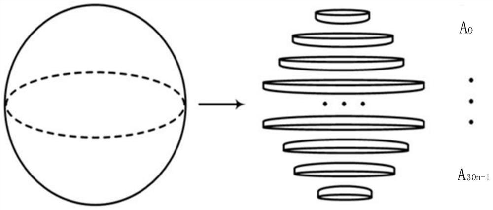
[0090] S1. According to the requirement of spatial clarity, the spherical surface is divided into 2688 annular surfaces with equally spaced latitude lines, and these annular surfaces are recorded as A in turn. i , i=0,1,...,2688;

[0091] Step 2, the toroidal surface A i Evenly divided into M ...

Embodiment 2

[0100] In this embodiment, the panoramic video minimum distortion mapping method is used to process a frame of image in the latitude and longitude format with a resolution of 8192×4096 in the panoramic video, and the panoramic video is a color video with three components. Suppose the color component used is YC b Cr , the sampling ratio is 4:2:0, and YC is still used after sampling b C r Indicates the color of each sampling point. Assume that the spatial resolution requirement is W=4928 for the Y component, H=1792 for the C b and C r The components are W=2462, H=896, and the quantization accuracy requirements are the same for each component, and they are all quantized to 256 levels.

[0101] For the Y component, perform the following steps:

[0102] S1. According to the requirement of spatial clarity, the spherical surface is divided into 2688 annular surfaces with equally spaced latitude lines, and these annular surfaces are recorded as A in turn. i , i=0,1,...,2688;

...


PUM


Abstract

The invention provides a panoramic video minimum deformation degree mapping method, which comprises the following steps of: according to a spatial definition requirement, dividing a spherical surface into 30n annular curved surfaces by using equally spaced latitude lines, and sequentially recording the annular curved surfaces as Ai, i = 0, 1,..., 30n-1; uniformly dividing the annular curved surface Ai into Mi areas by using equally spaced longitude lines, and calculating an average value of light rays in each area on the annular curved surface Ai as a sampling value of a sampling point corresponding to the area; and rearranging the sampling points into a rectangle according to a certain rule. According to the panoramic video minimum deformation degree mapping method provided by the invention, the sampling points can be uniformly sampled on the spherical surface as far as possible, the characteristics that the number of sampling points near the equator is large and the number of sampling points on two poles is small are kept, the inconsistency of rearranged image contents is reduced, and under the condition of achieving the same spatial definition, the problem of non-uniform sampling density is solved, and the compression efficiency is improved.

Description

technical field [0001] The technical field of panoramic video encoding of the present invention, in particular, relates to a method for mapping a panoramic video with minimum deformation degree. Background technique [0002] Panoramic video is an omnidirectional video that includes 360 degrees horizontally and 180 degrees vertically. The characteristics of high resolution and multiple viewing angles make it have a larger amount of information. At the same time, traditional video coding standards such as HEVC, VVC, AVS, etc. can only encode flat rectangular videos with the same resolution per frame, and cannot directly process spherical ones. Panoramic video. Therefore, studying how to sample from spherical video to planar video is a necessary process in the current study of panoramic video compression. [0003] The process of sampling from spherical video to planar video mainly includes three parts: mapping, sampling and rearranging. The essence of panoramic video mapping...

Claims


Application Information

Patent Timeline
IPC IPC(8): G06T7/11G06T7/90G06T9/00
CPCG06T7/11G06T7/90G06T9/00G06T2207/10016G06T2207/10024
Inventor 邢丹赵海武滕国伟
Owner SHANGHAI UNIV
Why Eureka
Try Eureka