Pre-alignment device and method of square substrates

A pre-alignment and substrate technology, which is applied to the exposure devices, optics, instruments, etc. of the photoengraving process, can solve the problems of robot handling errors, easy pollution, errors, etc., and achieves improved measurement accuracy, economic efficiency, and high alignment accuracy. Effect

Active Publication Date: 2015-07-22
SHANGHAI MICRO ELECTRONICS EQUIP (GRP) CO LTD
View PDF5 Cites 0 Cited by
  • Summary
  • Abstract
  • Description
  • Claims
  • Application Information

AI Technical Summary

Problems solved by technology

[0003] The position deviation of the square substrate in the loading box and the handling error of the robot will cause errors when the square substrate is loaded for the first time
If the loading accuracy does not meet the requirements of the lithography machine, the next process cannot be carried out
[0004] The prior art provides a mechanical detection method based on a contact sensor, which is characterized in that a position sensor is placed on the carrier platform to achieve pre-alignment of the square substrate; the disadvantage is that the contact alignment method is easy to contaminate and damage the square substrate. In addition, the solution has very strict requirements on the stability of the position sensor
[0005] Another existing technology is to realize the pre-alignment of the square substrate on the manipulator. The general scheme is as follows: place two CCDs above a certain fixed position of the manipulator, and the two CCDs collect the edge information of the square substrate through the optical lens. , and then use the edge information collected in the previous step to detect the position of the square substrate, compare it with the ideal position of the square substrate, and obtain the current rotation and displacement of the square substrate, thereby adjusting the position of the manipulator to achieve the purpose of adjusting the position of the square substrate; The disadvantage of the solution is that after pre-alignment on the manipulator, the square substrate needs to be placed on the workpiece table, and errors are inevitably introduced during the placement process, resulting in a decrease in alignment accuracy.
Another disadvantage is that this scheme tries to extract the edge information of the square substrate through the illumination on one side of the CCD, and the amount of edge information obtained through such an illumination method is very limited

Method used


Image

  • Pre-alignment device and method of square substrates
  • Pre-alignment device and method of square substrates
  • Pre-alignment device and method of square substrates

Examples


Embodiment Construction

[0023] In order to better understand the technical content of the present invention, specific embodiments are given together with the attached drawings for description as follows.

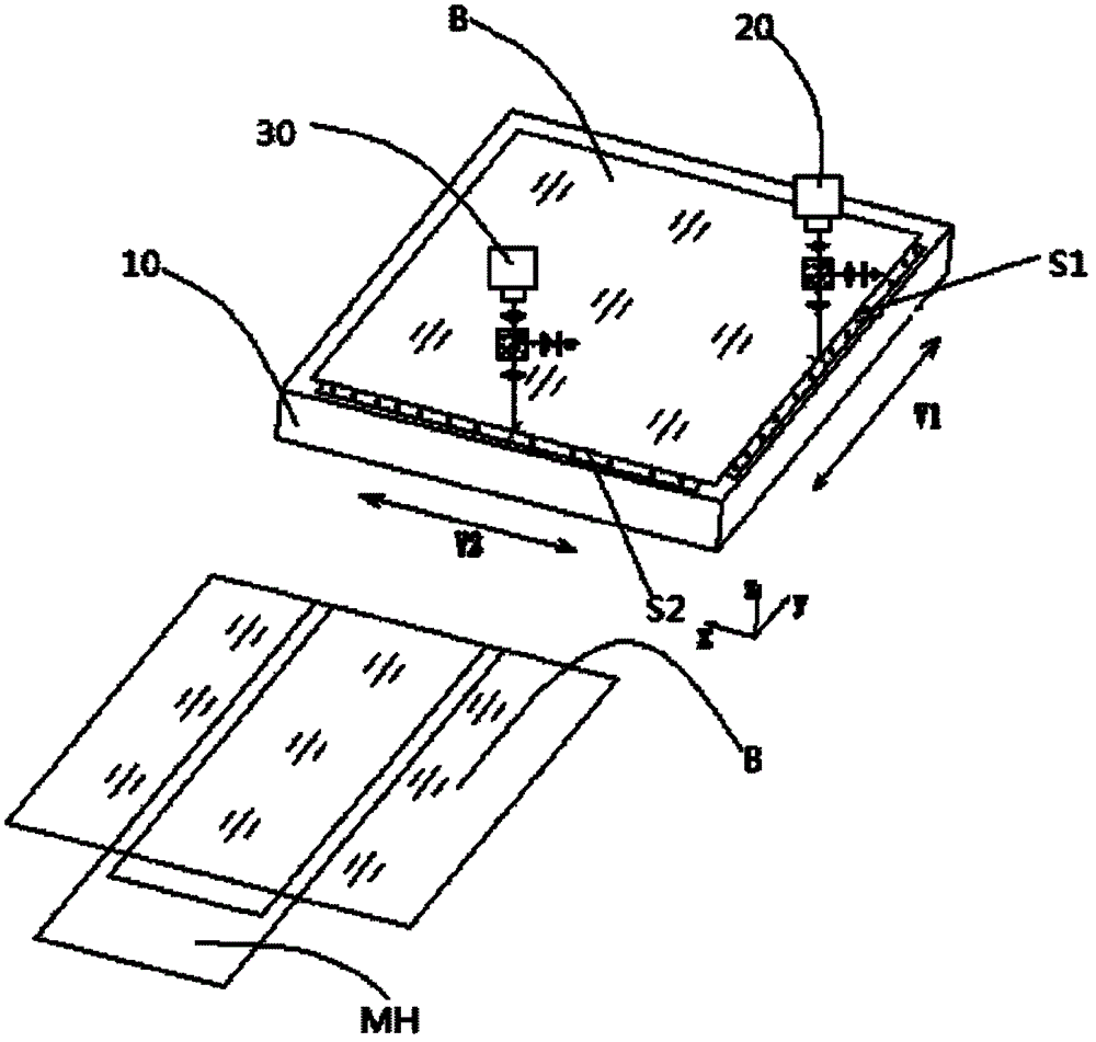
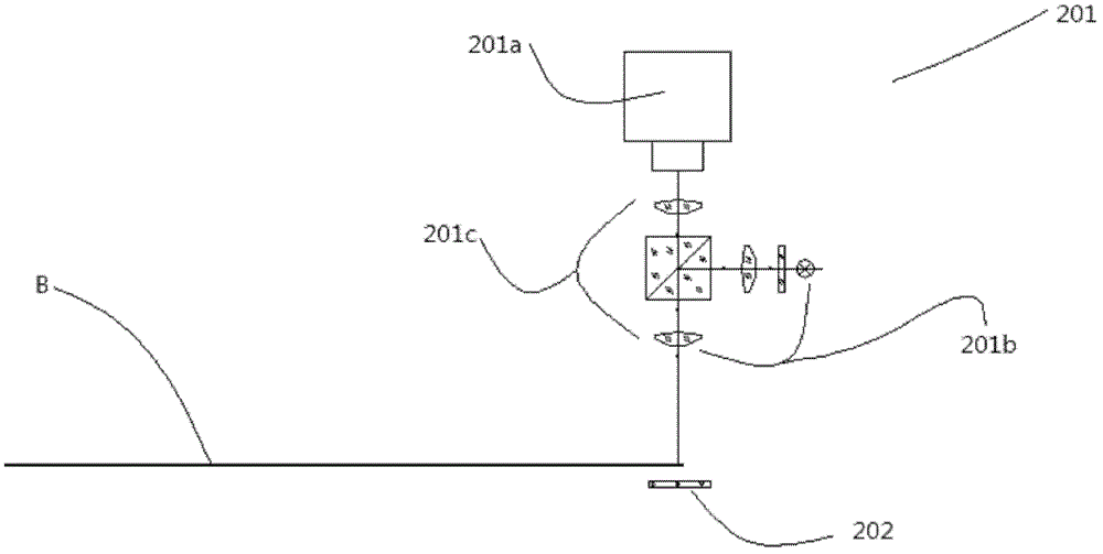
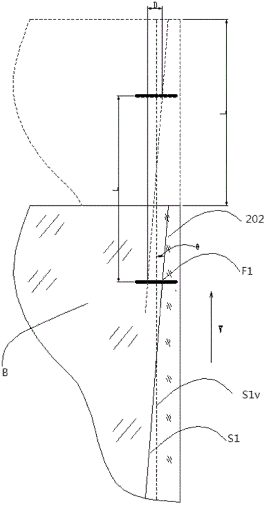
[0024] figure 1 Shown is a schematic diagram of a square substrate pre-alignment device according to an embodiment of the present invention, figure 2 is the main view of the detector, image 3 yes figure 1 The top view of the detector, Figure 4 It is a comparison diagram of the ideal substrate position and the actual post-chip substrate position. Please also refer to Figure 1 to Figure 4 .

[0025] The square substrate pre-alignment device is used to pre-align the square substrate transported by the manipulator to the workpiece table, including the workpiece table 10, the first detector 20, the second detector 30 and the controller (not shown in the figure). Wherein, the workpiece table 10 carries a square substrate B, the first detector 20 scans the first edge S1 of the square substrate, ...


PUM


Abstract

The invention provides a pre-alignment device and method of square substrates. The pre-alignment device of the square substrates is used for measuring the piece feeding error (eccentricity and deviation of substrates) of a mechanical arm in the substrate transmission process, and the measurement process is named as pre-alignment. In the method, a mechanical arm, a workpiece platform, a first detector, a second detector and a controller are mainly adopted, wherein the square substrates are loaded on the workpiece platform, the first detector is used for scanning the first edges of the square substrates and calculating the deviation values of the first edges; the second detector is used for scanning the second edges of the square substrates and calculating the deviation values of the second edges, and the second edges are vertical to the first edges; the controller is used for controlling and driving the workpiece platform according to the deviation values of the first edges and the deviation values of the second edges. The pre-alignment device and method of the square substrates, provided by the invention, generate no damage to the square substrates, save the time and improve the economic efficiency. Since an edge scanning surface manner is adopted, numerous sampling points are adopted and are close to the actual states of the edges, thereby improving the measuring precision.

Description

technical field [0001] The invention relates to a substrate processing system, and in particular to a square substrate pre-alignment device and method. Background technique [0002] In today's information society, displays are playing an increasingly important role in people's lives. In today's display field, the 100-year-old CRT (Cathode Ray Tube) is gradually being replaced by the Flat Panel Display (FPD) represented by the LCD (Liquid Crystal Display), and the newly emerged OLED (Organic Light Emitting Display) represented The new flat-panel display will provide people with more ideal display images and have a huge impact on the existing display industry structure. OLED is considered to be the most powerful competitor of LCD because of its advantages of ultra-thin, active light emission, high brightness, high contrast, wide viewing angle, wide operating temperature range, low power consumption, low cost, and all solid state. The fabrication of OLEDs relies on photolitho...

Claims


Application Information

Patent Timeline
Patent Type & Authority Patents(China)
IPC IPC(8): G03F7/20G03F9/00H01L21/68
Inventor 贾翔
Owner SHANGHAI MICRO ELECTRONICS EQUIP (GRP) CO LTD
Why Eureka
Try Eureka