Design method of superfine powder concentrator based on coarse and fine separation of semi-finished products

A design method and semi-finished technology, applied in the direction of solid separation, chemical instruments and methods, design optimization/simulation, etc., can solve the problems of low powder selection efficiency, coarse running, and increased energy consumption of powder separators

Active Publication Date: 2021-09-10
TIANJIN CEMENT IND DESIGN & RES INST +1
View PDF8 Cites 1 Cited by
  • Summary
  • Abstract
  • Description
  • Claims
  • Application Information

AI Technical Summary

Problems solved by technology

The cycle load refers to the ratio of the amount of powder returned by the classifier to the amount of finished products. When the efficiency of the classifier is low, the cycle load increases. From the perspective of productivity, the energy exerted by the classifier is not fully utilized.
[0003] The semi-finished product refers to the material that has been removed from the large particles through the previous sorting. The traditional semi-finished product sorting is to directly bring this part of the semi-finished product into the dynamic powder separator with the airflow for coarse and fine separation. This process

Method used


Image

  • Design method of superfine powder concentrator based on coarse and fine separation of semi-finished products
  • Design method of superfine powder concentrator based on coarse and fine separation of semi-finished products
  • Design method of superfine powder concentrator based on coarse and fine separation of semi-finished products

Examples


Embodiment Construction

[0053] In order to make the object, technical solution and advantages of the present invention more clear, the present invention will be further described in detail below in conjunction with the examples. It should be understood that the specific embodiments described here are only used to explain the present invention, not to limit the present invention.

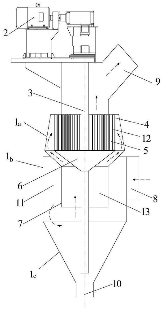
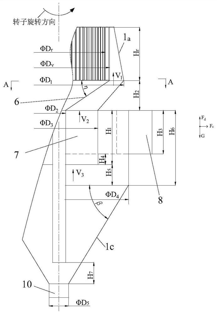
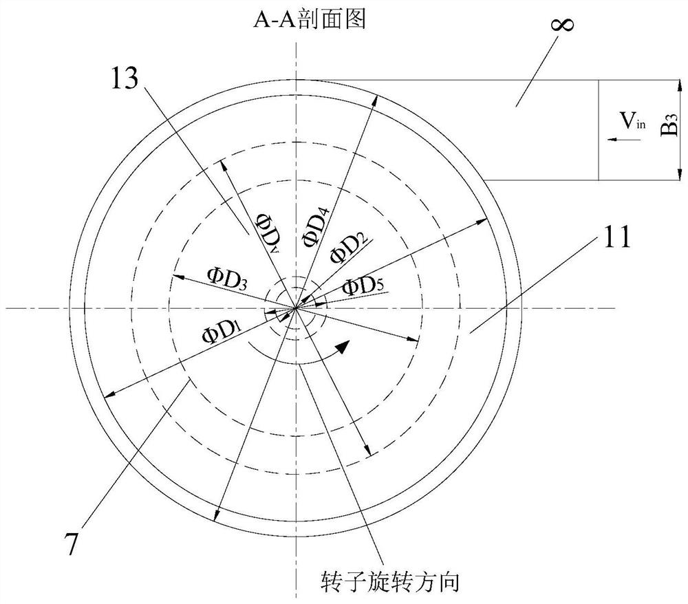
[0054] see Figure 1 to Figure 4 , a design method for ultra-fine powder separator based on semi-finished product thickness separation, including powder separator shell, which is divided into upper shell 1 a , in case 1 b And the lower shell (collecting cone) 1 c ; The bottom of the lower shell is connected to the coarse powder outlet 10; the lower shell (collecting cone) 1 c Angle with horizontal line β=45~80°; air inlet 8 enters middle housing 1 tangentially b ; The air inlet 8 can be a single air inlet or a double air inlet type; the upper casing 1 a The outer ring of the middle part is provided with guide vanes 4, ...


PUM


Abstract

The invention discloses a design method of a superfine powder concentrator based on coarse and fine separation of semi-finished products. The superfine powder concentrator comprises a shell, a guide vane and a cage type rotor, wherein a coarse powder discharge port is formed in the bottom of the lower shell; a dynamic powder concentrating, returning and discharging hopper is arranged at the portion, on the lower part of the guide vane, in the shell; the portion, on the outer side of the dynamic powder concentrating, returning and discharging hopper, on the lower part of the cage type rotor is sleeved with a guide device; the guide device comprises a cone part positioned at the upper part and a straight cylinder part positioned at the lower part and is installed on the lower part of the guide vane; the upper shell and the middle shell are separated by the cone part of the guide device; the straight cylinder part of the guide device is positioned on the outer side of the dynamic powder concentrating, returning and discharging hopper so that an inner cylinder and outer cylinder structure can be formed in a static powder selecting area. According to the design method, the static powder concentrating area is additionally arranged in front of a dynamic powder concentrating area, material-carrying airflow is forced to enter the dynamic powder concentrating area from an inner cylinder, the dust collecting efficiency of coarse particles in semi-finished product particles is greatly improved, and the superfine powder concentrating process is facilitated; and the airflow entering the guide vane is distributed more evenly, materials entering a dynamic powder concentrator are closer to finished products, the powder concentrating efficiency is greatly improved, and the circulation load of the dynamic powder concentrator is greatly reduced.

Description

technical field [0001] The invention belongs to the technical field of grinding, and in particular relates to a design method of an ultra-fine powder separator based on the separation of the thickness of semi-finished products. Background technique [0002] Powder classifier is a kind of equipment that relies on air medium to sort materials. It is an important part of the grinding system. Its performance directly affects the technical and economic indicators of the entire system. Most of the existing dynamic powder separators use cage rotors with different blade structures as the core components, and the cage rotors rotate at high speed to generate rotating airflow, forming a dynamic powder selection area. After the particles to be selected enter the dynamic powder selection area, mainly under the balance of centrifugal force, airflow drag force and their own gravity, the coarse particles fall into the discharge hopper to form return materials, and the fine particles move to...

Claims


Application Information

Patent Timeline
IPC IPC(8): B07B7/083B07B11/00B07B11/06G06F30/28
CPCB07B7/083B07B11/00B07B11/06G06F30/28
Inventor 王维莉豆海建石国平李洪刘畅李利恒
Owner TIANJIN CEMENT IND DESIGN & RES INST
Why Eureka
Try Eureka