Flotation production line

A production line and flotation technology, applied in flotation, chemical/physical/physicochemical fixed reactors, solid separation, etc., can solve the problem of increasing the cycle load of flotation machines, improving flotation recovery rate, unfavorable cost reduction and efficiency increase To achieve stable flotation process indicators, improve flotation recovery rate, and improve the effect of mineralization reaction

Pending Publication Date: 2020-02-28
PANGANG GRP MINING
View PDF0 Cites 0 Cited by
  • Summary
  • Abstract
  • Description
  • Claims
  • Application Information

AI Technical Summary

Problems solved by technology

However, the flotation agent often floats on the top layer of the mixing tank, and fails to fully enter the return pipe to participate in the mineralization reaction, that is, the diffused pulp enters the flotation machine from the overflow port.
As a result, there is the problem of insufficient mineralization reaction in the mixing tank of the floating titanium process, and it is difficult for the flotation agent to achieve the effect of changing the hydrophobicity of the ilmenite surface. This not only increases the cycle load of the flotation machine, but also reduces the flotation efficiency, resulting in The waste is not conducive to cost reduction and efficiency increase and the improvement of flotation recovery rate

Method used


Image

  • Flotation production line

Examples


Embodiment Construction

[0021] The technical solutions in the embodiments of the present invention will be clearly and completely described below with reference to the accompanying drawings in the embodiments of the present invention. Obviously, the described embodiments are only a part of the embodiments of the present invention, but not all of the embodiments. Based on the embodiments of the present invention, all other embodiments obtained by those of ordinary skill in the art without creative efforts shall fall within the protection scope of the present invention.

[0022] In order to make those skilled in the art better understand the solution of the present invention, the present invention will be further described in detail below with reference to the accompanying drawings and specific embodiments.

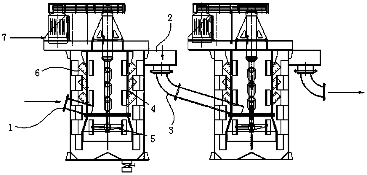
[0023] Please refer to figure 1 , figure 1 It is a schematic diagram of the structure of the flotation production line provided by the present invention.

[0024] The flotation production line p...


PUM


Abstract

The invention discloses a flotation production line. The flotation production line comprises at least two stirring barrels connected to feeding pipes, an overflow port is formed in the top of each stirring barrel, a discharging pipe is arranged at the bottom of each overflow port, and the discharging pipes can be connected to the feeding pipes so that all the stirring barrels can be connected in series. The flotation production line comprises at least two stirring barrels, the stirring barrels are connected in series, and ore pulp enters the previous stirring barrel through the feeding pipe, flows out from the overflow port after being stirred and then flows into the next stirring barrel along the discharging pipe. Although the in-series connection of the stirring barrels shortens the retention time of ore pulp in a single stirring barrel, the process requirement of the stirring time can be met by adjusting the number of barrels connected in series and the volume of the single barrel.Ore pulp and a flotation agent can be fully stirred in the stirring barrel, so that the ore surfaces are fully mixed with the flotation agent, and the mineralization reaction effect is improved. The consumption of a flotation reagent is reduced, the waste of the flotation reagent is avoided, and the circulating load of the flotation machine can be greatly reduced, so that the flotation process index is more stable and the flotation recovery rate is obviously improved.

Description

technical field [0001] The invention relates to the technical field of mineral flotation, in particular to a flotation production line. Background technique [0002] The flotation method is to add a flotation agent to the minerals to improve the hydrophobicity of the mineral surface, and then use the surface tension of the liquid to make the minerals that have reached the surface hydrophobic attached to the surface of the bubbles, and float with the bubbles to sort the target minerals from the ore. come out. [0003] In the preparation stage of the floating titanium process of the existing flotation production line, in order to achieve the process residence time in the single-stage mixing tank of the pulp, a single-stage mixing tank is used for the mixing and stirring operation of the chemicals. However, the flotation agent often floats on the top layer of the mixing tank, and cannot all enter the return pipe to participate in the mineralization reaction, that is, it enters...

Claims


Application Information

Patent Timeline
Patent Type & Authority Applications(China)
IPC IPC(8): B01J19/18B03D1/16
CPCB01J19/1862B03D1/16
Inventor 余强李小鹏
Owner PANGANG GRP MINING
Why Eureka
Try Eureka