
A power frequency induction electromagnetic boiler with a circulation heating system and its application method

A circulating heating and power frequency technology, which is applied in the control of fluid heaters, water heaters, fluid heaters, etc., can solve problems such as thermal environmental pollution, poor energy efficiency ratio, and affecting environmental performance of boilers, and achieve good heat exchange effects Effect

Active Publication Date: 2022-06-24
丹阳市汉德瑞工具有限公司
View PDF18 Cites 0 Cited by
  • Summary
  • Abstract
  • Description
  • Claims
  • Application Information

AI Technical Summary

Problems solved by technology

[0003] 1. The energy efficiency ratio of the traditional boiler is relatively poor due to the indirect heating and the heat conduction of the air medium when it is in use, resulting in the loss of thermal efficiency of the boiler during the heating process, which not only seriously increases the heating cost of the boiler, but also increases the heat consumption. The loss of water also caused environmental pollution, which seriously affected the environmental protection performance of the boiler; 2. When the traditional boiler equipment is heated, the cold water is heated to the set temperature, and then the water is turned over and then the cold water is poured in, so that the water flow inside the boiler cannot always maintain the same temperature. and the same capacity, it is easy to have high and low water flow temperature and insufficient water consumption, which makes it difficult to guarantee the water supply efficiency of the boiler; therefore, it is necessary to design a power frequency induction electromagnetic boiler with a circulating heating system and its Instructions

Method used


Image

  • A power frequency induction electromagnetic boiler with a circulation heating system and its application method
  • A power frequency induction electromagnetic boiler with a circulation heating system and its application method
  • A power frequency induction electromagnetic boiler with a circulation heating system and its application method

Examples


Embodiment Construction

[0033] In order to make the technical means, creative features, achievement goals and effects realized by the present invention easy to understand, the present invention will be further described below with reference to the specific embodiments.

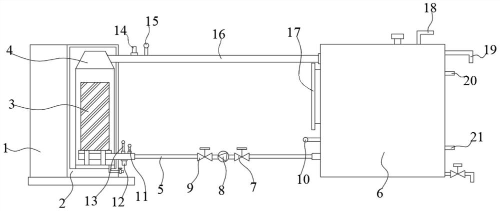
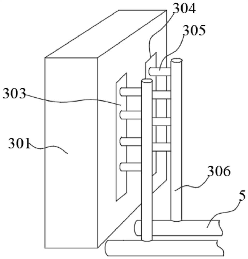
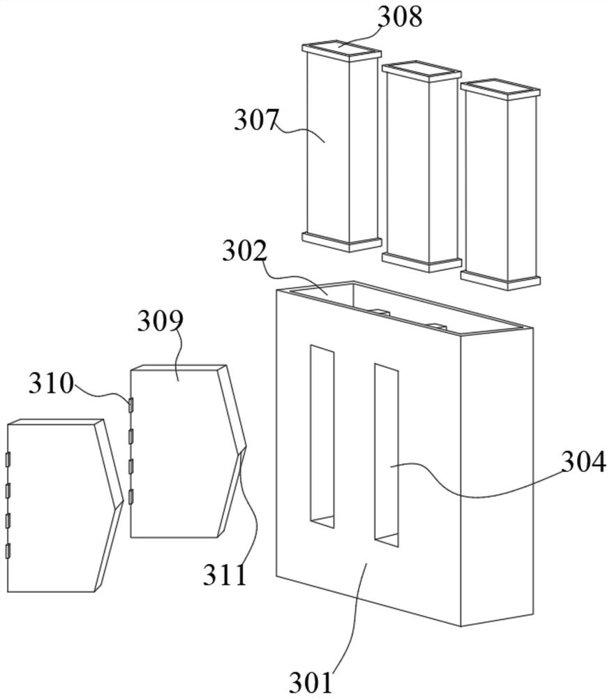
[0034] like Figure 1-4 As shown, a power frequency induction electromagnetic boiler with a circulating heating system and a method of using the same, including an electric control box 1, a circulating water tank 4, a heating mechanism 3 and a water storage tank 6, the right outer wall of the electric control box 1 is fixedly connected with a A protective casing 2, a circulating water tank 4 is installed inside the protective casing 2, and a heating mechanism 3 is arranged inside the circulating water tank 4, and one end of a water inlet pipe 5 is inserted into the inner side wall of the circulating water tank 4, and the water inlet pipe The other end of 5 extends to the left inner wall of the water storage tank 6, the inner side wal...


PUM


Abstract

The invention discloses a power frequency induction electromagnetic boiler with a circulating heating system and a method for using the boiler, which comprises an electric control box, a circulating water tank, a heating mechanism and a water storage tank. A circulating water tank is installed inside the protective shell, and a heating mechanism is arranged inside the circulating water tank; the present invention realizes that the thermal efficiency generated by the heating mechanism arranged in the circulating water tank can be fully absorbed by the water flow inside the circulating water tank, and its The short-circuit current on the secondary side reaches 1-46,000 amperes, and its magnetic field strength per phase reaches (1.4-5.2)x10A / m. With such a strong alternating magnetic field, the magnetic flux leakage induces a large eddy current in the circulating water tank, so that the secondary The side short-circuit heating box is the main heating body, which is directly installed in the circulating water, and the circulating water tank is the auxiliary heating body. The two heating bodies directly heat the medium water flowing through them. The heat exchange effect is good, and it is suitable for widespread promotion and application. use.

Description

technical field [0001] The invention relates to the technical field of power frequency induction electromagnetic boiler equipment, in particular to a power frequency induction electromagnetic boiler with a circulating heating system and a method of using the same. Background technique [0002] The heating methods of traditional coal-fired, oil-fired, gas-fired and electric heating pipes are flame or electric heating pipes, and then the surrounding medium water is heated by pipes. The heating methods of these traditional boilers are indirect heating, and the heat exchange efficiency of their products is bound to be affected. influences. In heat transfer, there is a basic theory: when the fluid flows through the surface of the heating element, the fluid close to the surface of the heating element is static due to the viscous effect, and the heat transfer can only be carried out in the way of heat conduction, and it occurs when it leaves the surface of the heating element. Hea...

Claims


Application Information

Patent Timeline
Patent Type & Authority Patents(China)
IPC IPC(8): F24H1/22F24H9/00F24H9/1818F24H9/20F24H15/37F24H15/34F24H15/215F24H15/219
CPCF24H1/225F24H9/0005F24H9/1818F24H9/2028F24H2250/08
Inventor 戎彪
Owner 丹阳市汉德瑞工具有限公司
Learn More