
Scraper conveyor fault diagnosis system and method

A fault diagnosis system and technology of scraper conveyor, which is applied in the testing of mechanical components, testing of machine/structural components, instruments, etc., can solve problems such as loss, harsh working environment of scraper conveyor, and variable workload

Active Publication Date: 2021-09-10
CHINA UNIV OF MINING & TECH +1
View PDF15 Cites 0 Cited by
  • Summary
  • Abstract
  • Description
  • Claims
  • Application Information

AI Technical Summary

Problems solved by technology

[0002] The scraper conveyor is an indispensable and important conveying equipment in coal mines. It is mainly used to transport materials such as coal or gangue. It is also used as the fulcrum of the hydraulic support and the running track of the coal shearer. Factors such as heavy weight and harsh underground environment make it prone to failure, and other equipment will also fail to operate, which affects the normal operation of the entire system and has a certain negative impact on production efficiency; the reducer operates as a scraper conveyor The key device in the process, which works in a dusty and humid environment with a lot of coal slag, and is affected by the specification of falling coal, has a variable workload, and its internal gear bearings and other key components are easily damaged and cause failures. Under this influence, the deceleration Machine failure will cause the entire coal mining workflow, resulting in huge losses, and even lead to major safety accidents, seriously affecting safe production
[0003] The traditional scraper conveyor fault diagnosis is analyzed by collecting vibration signals. The disadvantages are: (1) The vibration signal collection sensor belongs to direct contact measurement. Under normal working conditions, screw connections are often used. In the case of vibration, the connection will be loosened and the sensor will be damaged. Due to the harsh working environment of the scraper conveyor, it is not suitable to use contact measurement in many cases; in addition, because the sensor uses direct contact measurement, it will cause sensor resonance. The useful information in the signal causes serious interference; (2) When the vibration sensor is installed, the equipment shell needs to be processed. If the installation position is not good, the effect characteristics of the collected vibration signal are very weak, and frequent replacement of the installation position will seriously damage the equipment. Housing, poor adjustability of sensor mounting position
The device in this application adopts a multi-sensor arrangement, which can improve the effectiveness of vibration signal acquisition, but it still cannot effectively avoid the influence of interference signals on diagnostic results

Method used


Image

  • Scraper conveyor fault diagnosis system and method
  • Scraper conveyor fault diagnosis system and method
  • Scraper conveyor fault diagnosis system and method

Examples


Embodiment 1

[0058] The vibration signal sensor used in traditional scraper conveyor fault diagnosis is in direct contact with the scraper conveyor, which has poor adjustability, and the working environment of the scraper conveyor is harsh. On the one hand, it is easy to damage the sensor structure; Serious interference will be caused to the signal, which will eventually make it difficult to obtain accurate and effective diagnostic information. In view of the above problems, this embodiment designs a scraper conveyor fault diagnosis system.

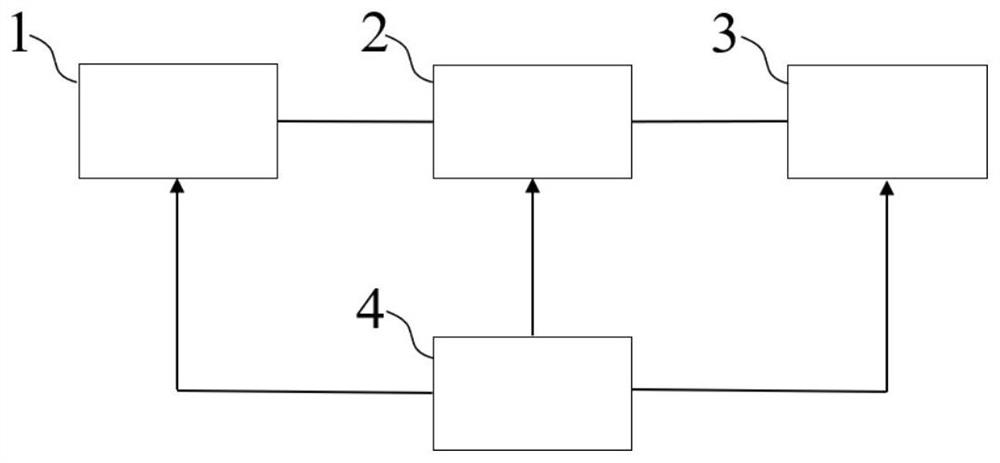
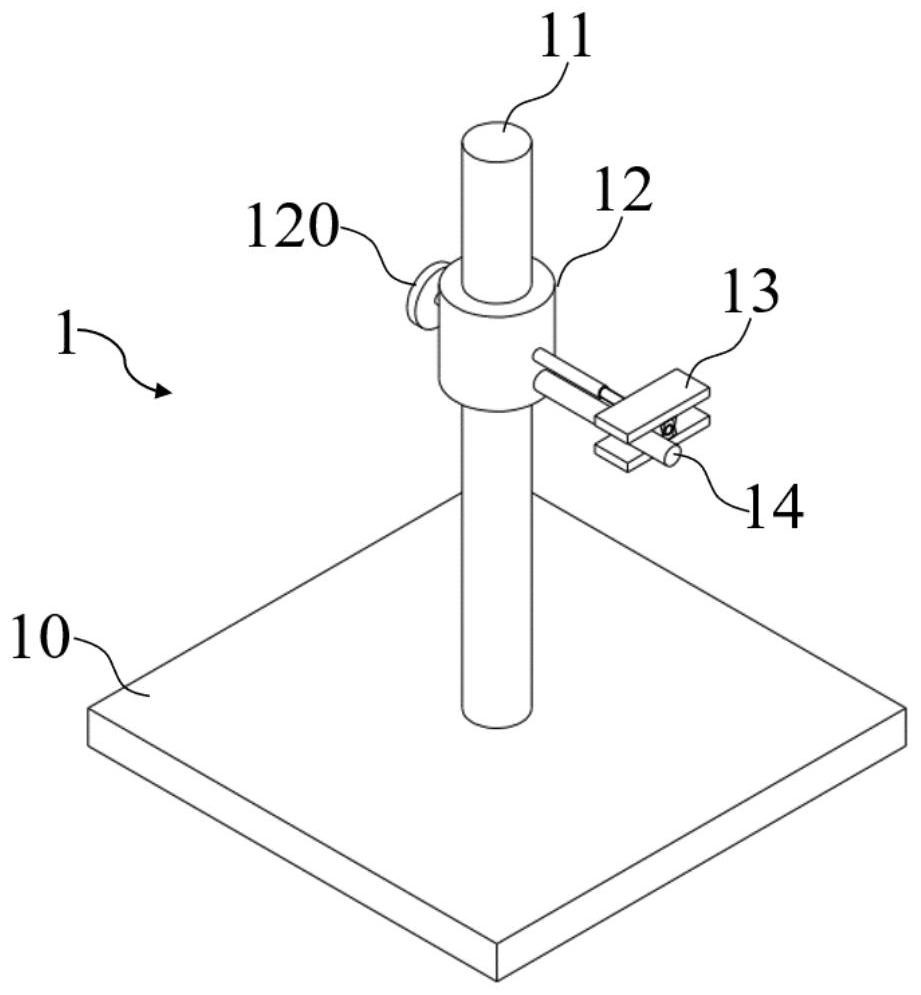
[0059] Such as figure 1 As shown, the scraper conveyor fault diagnosis system of this embodiment is composed of an acoustic signal acquisition module 1, a processing terminal 2, an interactive module 3 and a power supply 4, wherein the acoustic signal acquisition module 1 includes an acquisition terminal, a signal conditioning unit and a lower computer, The three are sequentially connected by signal. The acquisition end is arranged beside the shaft en...

Embodiment 2

[0064] This embodiment provides a method for fault diagnosis of a scraper conveyor, the method flow chart is as follows Figure 4 As shown, the scraper conveyor fault diagnosis system based on Embodiment 1 aims to solve the problem that interference factors affect the accuracy of diagnosis results when diagnosing sound signals. The steps are as follows:

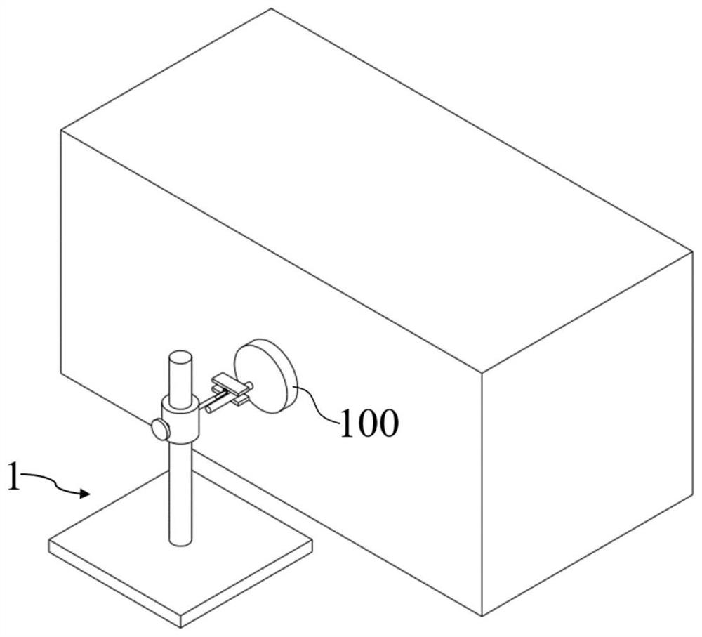
[0065] S1. Arrange the acquisition end of the acoustic signal acquisition module 1 on the side of the shaft end 100. The acquisition end of this embodiment is provided with a microphone 14, which is arranged towards the center of the shaft end 100. The microphone 14 collects the sound emitted by the shaft end 100 when the reducer is started. After the sound signal is amplified by the signal conditioning unit, the lower computer transmits the collected sound signal as the original sound signal to the processing terminal 2;

[0066] S2. The processing terminal 2 processes the original sound signal, and first decomposes the orig...


PUM


Abstract

The invention discloses a scraper conveyor fault diagnosis system and method, and belongs to the technical field of coal mining equipment diagnosis. The diagnosis system comprises: an acoustic signal acquisition module, wherein the acoustic signal acquisition module comprises an acquisition end, a signal conditioning unit and a lower computer, and the acquisition end is arranged beside the shaft end of a scraper conveyor speed reducer driving box; a processing terminal which diagnoses whether the speed reducer corresponding to the acoustic signal has a fault or not; an interaction module which is in signal connection with the processing terminal and presents the diagnosis result and the collected acoustic signal to a user; and a power supply which supplies power to the acoustic signal acquisition module, the processing terminal and the interaction module. After EMD decomposition is carried out on an original sound signal, the most sensitive IMF component is screened out, the modal aliasing segment is eliminated, then filtering reconstruction is carried out, and the modal aliasing phenomenon in the EMD decomposition process is effectively solved, so the signal features are more remarkable; and after VMD decomposition is carried out on the reconstructed signal, envelope spectrum analysis is carried out on the most sensitive imf component signal, so an accurate and effective diagnosis result is obtained, and the diagnosis and maintenance efficiency is greatly improved.

Description

technical field [0001] The invention belongs to the technical field of coal mining equipment diagnosis, and more specifically relates to a fault diagnosis system and a diagnosis method of a scraper conveyor. Background technique [0002] The scraper conveyor is an indispensable and important conveying equipment in coal mines. It is mainly used to transport materials such as coal or gangue. It is also used as the fulcrum of the hydraulic support and the running track of the coal shearer. Factors such as heavy weight and harsh underground environment make it prone to failure, and other equipment will also fail to operate, which affects the normal operation of the entire system and has a certain negative impact on production efficiency; the reducer operates as a scraper conveyor The key device in the process, which works in a dusty and humid environment with a lot of coal slag, and is affected by the specification of falling coal, has a variable workload, and its internal gear ...

Claims


Application Information

Patent Timeline
IPC IPC(8): G01M13/028G01M13/025G06F17/18
CPCG01M13/028G01M13/025G06F17/18
Inventor 江帆朱真才吴镇阳彭玉兴卢明立周公博李伟闵令江曹国华江峰沈熙
Owner CHINA UNIV OF MINING & TECH
Learn More