Underwater sound source positioning and signal acquisition method based on distributed sound wave sensing technology

A technology of acoustic wave sensing and sound source location, applied in positioning, radio wave measurement systems, instruments, etc., can solve the problem that the redundant information of perception data has not been fully tapped and utilized, and the specific direction and spatial position of underwater sound sources cannot be obtained And other issues

Active Publication Date: 2021-09-10
HUAZHONG UNIV OF SCI & TECH
View PDF6 Cites 0 Cited by
  • Summary
  • Abstract
  • Description
  • Claims
  • Application Information

AI Technical Summary

Problems solved by technology

[0007] The existing distributed underwater acoustic wave sensing technology based on distributed acoustic wave sensing technology cannot obtain the specific direction and spatial position of the underwater sound source, and its perception data contains a large amount of spatially related redundant information, which has not yet been fully exploited. and the problem of utilization, the present invention designs a kind of underwater sound source localization and signal acquisition method based on distributed acoustic wave sensing technology, aims to realize the fast and accurate localization and type judgment of large-scale underwater target, carry out position tracking, And realize the recovery and acquisition of high signal-to-noise ratio signals from various sound sources

Method used


Image

  • Underwater sound source positioning and signal acquisition method based on distributed sound wave sensing technology
  • Underwater sound source positioning and signal acquisition method based on distributed sound wave sensing technology
  • Underwater sound source positioning and signal acquisition method based on distributed sound wave sensing technology

Examples


Embodiment Construction

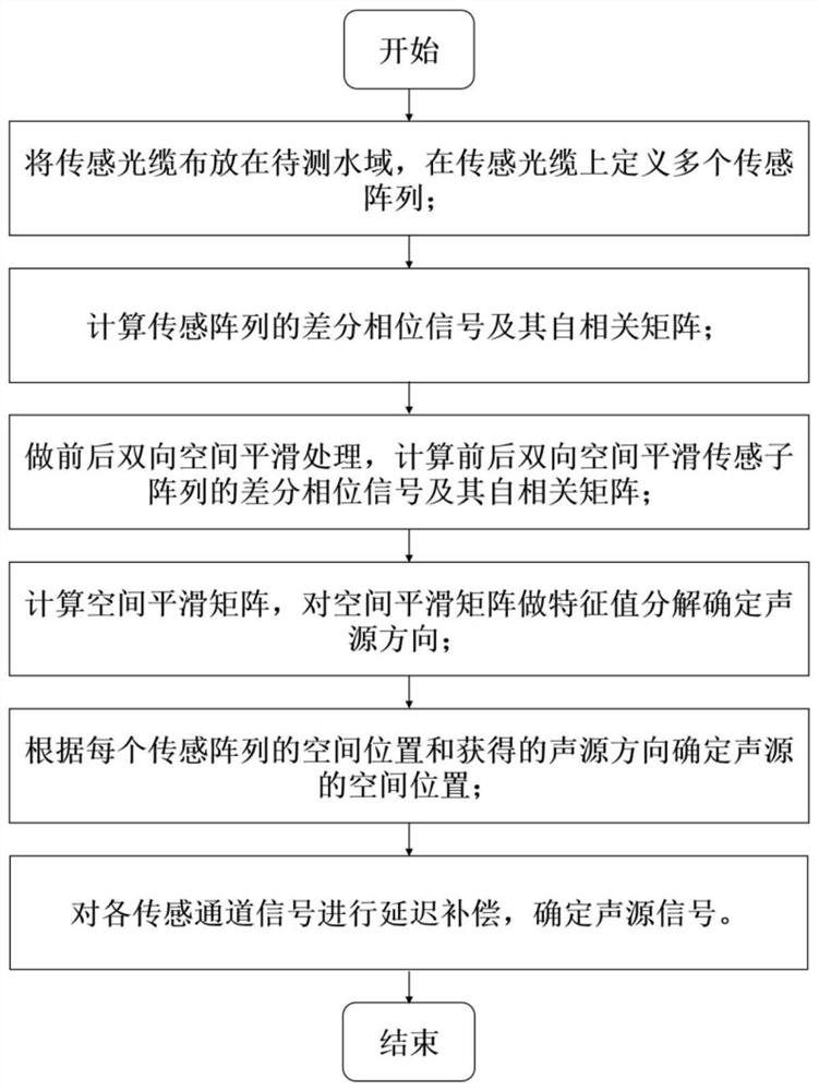
[0058] In order to make the purpose, technical solution and advantages of the present invention more clear, the present invention will be further described below in conjunction with the accompanying drawings and embodiments. It should be understood that the specific embodiments described here are only used to explain the present invention, not to limit the present invention.

[0059] Such as figure 1 As shown, the embodiment of the present invention provides a two-dimensional and three-dimensional underwater sound source positioning and a high signal-to-noise ratio signal acquisition method based on distributed acoustic wave sensing technology, including:

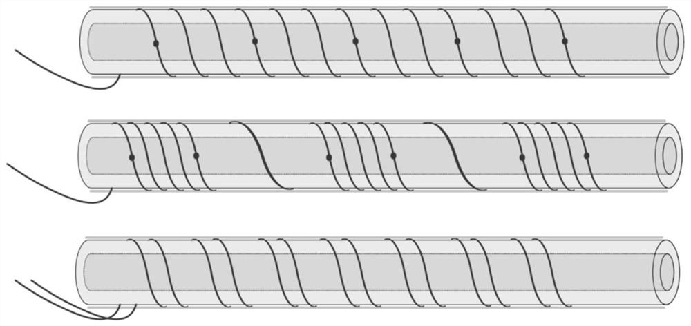
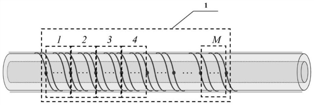
[0060] (1) Lay the sensing optical cable in the water area to be tested, and define multiple sensing arrays on the sensing optical cable. Each sensing array contains a number of continuous sensing channels that meet the far-field conditions of the sound source. Each sensing The sound source far-field condition is not satis...


PUM


Abstract

The invention discloses an underwater sound source positioning and signal obtaining method based on a distributed sound wave sensing technology, and belongs to the field of underwater sound source detection. The method comprises the following steps: defining a plurality of sensing arrays on sensing optical cables distributed in a water area to be detected; demodulating the acquired backward scattering light signal of the sensing optical cable to obtain a differential phase signal of each sensing array and an autocorrelation matrix of the differential phase signals; performing front-back bidirectional spatial smoothing processing on a plurality of sensing channels of each sensing array, constructing front-back bidirectional spatial smoothing sensing sub-arrays, and obtaining differential phase signals of the front-back bidirectional spatial smoothing sensing sub-arrays and an autocorrelation matrix thereof; calculating a spatial smooth matrix, and performing eigenvalue decomposition on the spatial smooth matrix to determine a sound source direction; determining the spatial position of the sound source according to the spatial position of each sensing array and the obtained sound source direction; and performing delay compensation on each sensing channel signal, and determining a sound source signal. According to the invention, the distributed sound wave sensing signals are processed, so that accurate sound source positioning and signal acquisition are realized.

Description

technical field [0001] The invention relates to the field of underwater sound source detection, and more specifically, to an underwater sound source location and signal acquisition method based on distributed acoustic wave sensing technology. Background technique [0002] In recent years, with people's attention to the ocean, the importance of ocean detection has become more prominent and has become the focus of research. Acoustic signal is currently the only known form of energy that can be transmitted over long distances in seawater. Using sound waves as information carriers to monitor the acoustic characteristics of underwater targets is an important tool in underwater resource exploration, marine seismic monitoring, and military anti-submarine. advanced means. As a new product of the combination of advanced optical fiber optoelectronic technology and underwater acoustic engineering technology, fiber optic hydrophone has the advantages of light weight, small size, strong...

Claims


Application Information

Patent Timeline
Patent Type & Authority Applications(China)
IPC IPC(8): G01S5/22
CPCG01S5/22Y02A90/30
Inventor 孙琪真陈俊峰孙翌翔杨子蕴闫志君
Owner HUAZHONG UNIV OF SCI & TECH
Why Eureka
Try Eureka