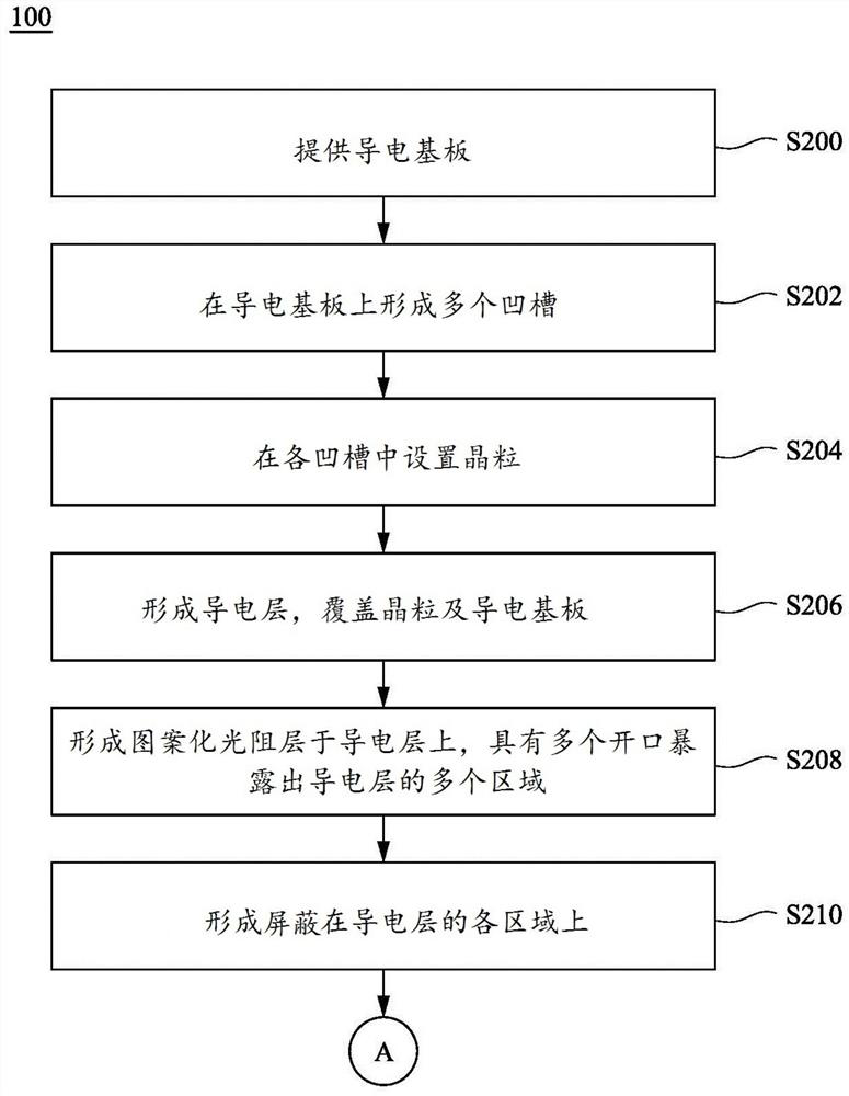
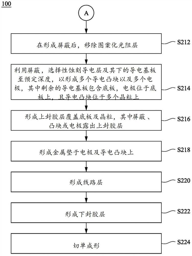
Manufacturing method of grain packaging structure
A technology of packaging structure and manufacturing method, applied in semiconductor/solid-state device manufacturing, electrical components, electrical solid-state devices, etc., can solve the problems of power chip thermal energy not easily dissipated, time-consuming and labor-intensive, etc.
- Summary
- Abstract
- Description
- Claims
- Application Information
AI Technical Summary
Problems solved by technology
Method used
Image


Examples
Embodiment Construction
[0047] In order to make the description of the embodiments of the present invention more detailed and complete, the following provides illustrative descriptions for the implementations and specific examples of the present invention; but this is not the only form for implementing or using the specific embodiments of the present invention. The various embodiments disclosed below can be combined or replaced with each other when beneficial, and other embodiments can also be added to one embodiment, without further description or illustration.
[0048] In the following description, numerous specific details will be set forth in order to enable readers to fully understand the following embodiments. However, embodiments of the invention may be practiced without these specific details. In other instances, well-known structures and devices are only schematically shown in order to simplify the drawings.
[0049] In the embodiments and claims, "a" and "the" can generally refer to a sing...
PUM
| Property | Measurement | Unit |
|---|---|---|
| Thickness | aaaaa | aaaaa |
Abstract
Description
Claims
Application Information
 - R&D
- Intellectual Property
- Life Sciences
- Materials
- Tech Scout
- Unparalleled Data Quality
- Higher Quality Content
- 60% Fewer Hallucinations
Browse by: Latest US Patents, China's latest patents, Technical Efficacy Thesaurus, Application Domain, Technology Topic, Popular Technical Reports.
© 2025 PatSnap. All rights reserved.Legal|Privacy policy|Modern Slavery Act Transparency Statement|Sitemap|About US| Contact US: help@patsnap.com