
Rotor shaft with oil pipe and machining process of rotor shaft

A processing technology, rotor shaft technology, applied in the direction of electromechanical devices, electrical components, mechanical equipment, etc., can solve the problems of poor processing technology of rotor shaft, internal stress of rotor shaft, etc.

Pending Publication Date: 2021-09-10
EVERGRANDE NEW ENERGY AUTOMOTIVE INVESTMENT HLDG GRP CO LTD
View PDF6 Cites 1 Cited by
  • Summary
  • Abstract
  • Description
  • Claims
  • Application Information

AI Technical Summary

Problems solved by technology

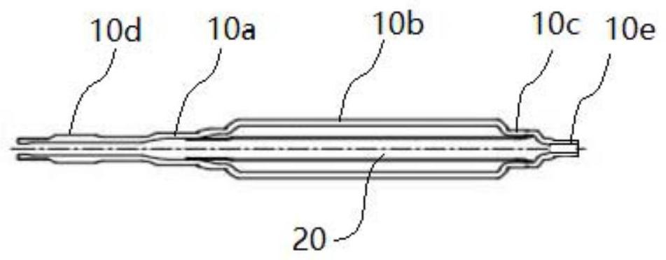
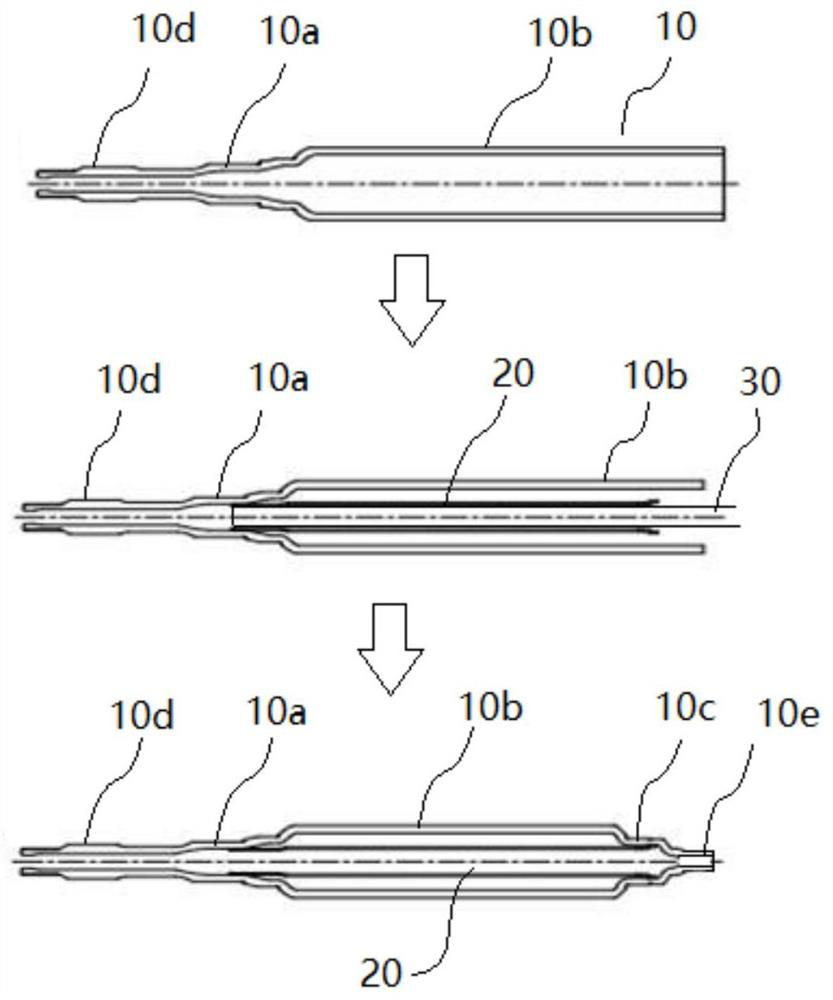
[0004] The technical problem to be solved in this application is that the poor processing technology of the existing rotor shaft leads to the problem that the rotor shaft has internal stress. Therefore, this application proposes a rotor shaft with oil pipes with good processing technology and its processing craft

Method used


Image

  • Rotor shaft with oil pipe and machining process of rotor shaft
  • Rotor shaft with oil pipe and machining process of rotor shaft

Examples


Embodiment Construction

[0026] The technical solutions of the present application will be clearly and completely described below in conjunction with the accompanying drawings. Apparently, the described embodiments are some of the embodiments of the present application, not all of them. Based on the embodiments in this application, all other embodiments obtained by persons of ordinary skill in the art without making creative efforts belong to the scope of protection of this application.

[0027] In the description of this application, it should be noted that the terms "center", "upper", "lower", "left", "right", "vertical", "horizontal", "inner", "outer" etc. The indicated orientation or positional relationship is based on the orientation or positional relationship shown in the drawings, and is only for the convenience of describing the present application and simplifying the description, rather than indicating or implying that the referred device or element must have a specific orientation, use a spec...


PUM


Abstract

The invention discloses a rotor shaft with an oil pipe and a machining process of the rotor shaft. The machining process of the rotor shaft comprises the following steps that: a hollow rotor shaft body is subjected to die forging, wherein the hollow rotor shaft body comprises a first hollow shaft section and a second hollow shaft section, and the pipe diameter of the first hollow shaft section is smaller than that of the second hollow shaft section; an oil pipe inserted with a mandrel is inserted into the hollow rotor shaft body, so that the first end of the oil pipe is matched with the first hollow shaft section; the first hollow shaft section is spun, so that partial area of the first hollow shaft section and the first end of the oil pipe are forged and pressed into a whole; the mandrel is taken out from the second end of the oil pipe; and the second hollow shaft section is spun, so that partial area of the second hollow shaft section and the second end of the oil pipe are forged and pressed into a whole to form a third hollow shaft section. With the rotor shaft with oil pipe and machining process of the rotor shaft adopted, the problem that an existing rotor shaft has internal stress due to the fact that the machining manufacturability of the rotor shaft is poor can be solved.

Description

technical field [0001] The present application relates to the field of design and manufacture of components of a motor rotor system, in particular to a rotor shaft with an oil pipe and its processing technology. Background technique [0002] Existing electric drive products use oil cooling to cool the motor rotor system. Usually, the rotor system of the motor is cooled efficiently by setting an oil pipe inside the rotor hollow shaft to form an oil passage and return it to the gearbox. [0003] At present, the method of installing the oil pipe in the hollow rotor shaft usually adopts the following process method. First, the first section shaft and the second section shaft that make up the hollow rotor shaft are respectively swaged or spin-formed; to make the oil pipe, use a press to press the oil pipe Install it on the second section of the shaft to achieve an interference fit with the mating surface; then press the other end of the oil pipe in the previous step onto the fir...

Claims


Application Information

Patent Timeline
IPC IPC(8): H02K7/00H02K9/19H02K15/00B21K1/06
CPCH02K7/003H02K9/19H02K15/00B21K1/063
Inventor 杨亚林马超
Owner EVERGRANDE NEW ENERGY AUTOMOTIVE INVESTMENT HLDG GRP CO LTD
Learn More