A cooling device for bearing forgings

A technology of cooling device and water cooling device, which is applied in the field of bearing processing, can solve the problems of reducing the air cooling effect and good ventilation of bearing forgings, and achieve the effect of maintaining the air cooling effect, reducing labor intensity and improving performance

Active Publication Date: 2022-06-17
临清市同兴轴承锻造有限公司
View PDF7 Cites 0 Cited by
  • Summary
  • Abstract
  • Description
  • Claims
  • Application Information

AI Technical Summary

Problems solved by technology

[0005] Through the above cooling process, it can be seen that because the bearing forgings 8 are laid flat and transferred to the air-cooled conveyor 2, the bearing forgings 8 in the flat state are not as good as the bearing forgings 8 in the upright state, which reduces the impact on the bearing forgings. 8 air cooling effect

Method used


Image

  • A cooling device for bearing forgings
  • A cooling device for bearing forgings
  • A cooling device for bearing forgings

Examples


Embodiment 1

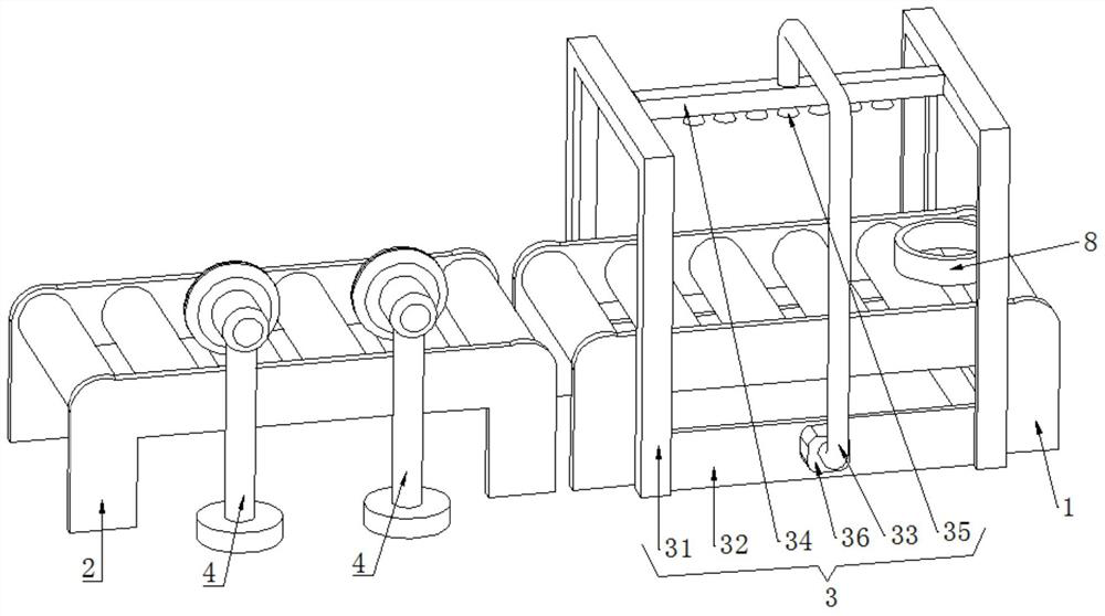
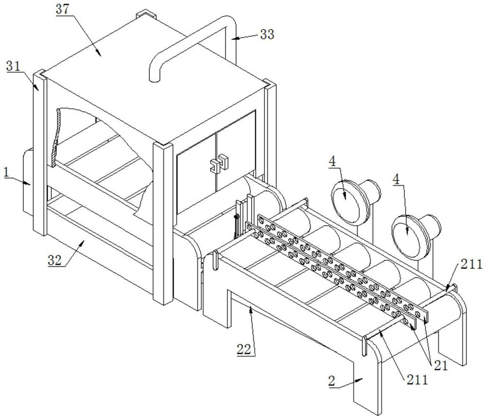
[0047] like Figure 2-6 As shown, a cooling device for a bearing forging includes a water-cooled conveyor 1 , an air-cooled conveyor 2 , a water-cooled device 3 , an air-cooled device 4 , and a turning mechanism 5 .

[0048] Both the water-cooled conveyor 1 and the air-cooled conveyor 2 can use a chain conveyor or a roller conveyor. The water-cooled conveyor 1 and the air-cooled conveyor 2 are placed on the ground in turn.

[0049] The water cooling device 3 includes a water cooling frame 31 , a protective box 37 , a collection tank 32 , a water supply pipe 33 , a water distribution pipe 34 , a spray head 35 , and a water pump 36 . The upper end of the water cooling rack 31 is welded with a protective box 37 , and the lower end of the water cooling rack 31 is welded with a collecting tank 32 . One end of the water supply pipe 33 is welded and fixed to the groove wall of the collection tank 32, the water supply pipe 33 is communicated with the inner cavity of the collection t...

Embodiment 2

[0062] like Figure 7-8 As shown, this Embodiment 2 makes further improvements on the basis of Embodiment 1.

[0063] In a cooling device for a bearing forging in the second embodiment, an auxiliary spray mechanism 6 is also included.

[0064] The auxiliary spray mechanism 6 includes an auxiliary telescopic rod 61, an auxiliary vertical rod 62, an auxiliary horizontal rod 63, a first spray seat 64, a second spray seat 65, a first auxiliary spray head 66, a second auxiliary spray head 67, and a connecting hose 68. Auxiliary hose 69.

[0065] The auxiliary telescopic rod 61 also adopts an electric push rod. The auxiliary telescopic rod 61 is arranged outside the protective box 37 , and the lower end of the auxiliary telescopic rod 61 is welded and fixed to the protective box 37 .

[0066] The upper end of the protective box 37 is provided with an installation hole 371 , and the upper end of the auxiliary vertical rod 62 passes through the installation hole 371 .

[0067] The ...

Embodiment 3

[0074] like Figure 9-10 As shown, this embodiment 3 makes further improvements on the basis of embodiment 2:

[0075] In a bearing forging cooling device of the third embodiment, the auxiliary spray mechanism 6 further includes a radial adjustment component 7 .

[0076] The radial adjustment assembly 7 is arranged in the protective box 37 , and the radial adjustment assembly 7 includes an adjustment sliding cylinder 71 , an adjustment telescopic rod 72 , an adjustment rod 73 , and an adjustment connecting rod 74 .

[0077] The adjusting slide cylinder 71 is sleeved on the auxiliary vertical rod 62 , and the adjusting slide cylinder 71 can slide up and down along the auxiliary vertical rod 62 .

[0078] The adjusting telescopic rod 72 also adopts an electric push rod. The upper end of the adjusting telescopic rod 72 is welded and fixed to the auxiliary vertical rod 62 , and the lower end of the adjusting telescopic rod 72 is welded and fixed to the adjusting sliding cylinder ...


PUM


Abstract

The invention discloses a bearing forging cooling device, which relates to the technical field of bearing processing, including a water-cooling conveyor, an air-cooling conveyor, a water-cooling device, an air-cooling device, a turning mechanism, the water-cooling conveyor and the air-cooling conveyor are connected, and the water-cooling conveyor There is a water-cooling device on the machine, and an air-cooling device on the air-cooled conveyor. The turning mechanism is located between the water-cooling conveyor and the air-cooling conveyor. The seat is connected with the air-cooled conveyor, the lower end of the flipping fixed plate is connected with the flipping seat, the lower end of the flipping movable plate is hinged with the flipping seat, the flipping telescopic rod is arranged on the side of the flipping movable plate away from the flipping fixed plate, and the lower end of the flipping telescopic rod is connected with The flipping seat is connected, and the upper end of the flipping telescopic rod is hinged with a flipping slider, and the flipping slider is slidably connected with the flipping movable plate. The invention can improve the air cooling effect on the bearing forging.

Description

technical field [0001] The invention relates to the technical field of bearing processing, in particular to a cooling device for a bearing forging. Background technique [0002] Bearings are an important component in contemporary machinery and equipment. Bearings include bearing rings (inner and outer rings), rolling elements, and cages. When processing bearing rings, the following forging process is first required: (1) heating the cylindrical blank, (2) using punching equipment to roughen and punch the cylindrical blank to obtain a ring-shaped blank , (3) Use a ring rolling machine to roll the billet of the annular structure, expand the inner diameter of the billet of the annular structure, and reduce the thickness of the billet of the annular structure. After the bearing ring is subjected to the above forging process, the bearing forging is obtained. The temperature of the bearing forging is relatively high, and then the bearing forging is cooled by a cooling device to i...

Claims


Application Information

Patent Timeline
Patent Type & Authority Patents(China)
IPC IPC(8): B21K29/00B21K1/04
CPCB21K29/00B21K1/04
Inventor 汪庆刚邢丕伟田兆志王纪军
Owner 临清市同兴轴承锻造有限公司
Why Eureka
Try Eureka