A collection vessel capable of removing cyanobacterial sludge

A cyanobacterial oil and cabin technology, which is applied in special purpose ships, general water supply conservation, and open water surface cleaning, etc., can solve problems such as hole blockage, fishery and aquaculture hazards, and affect equipment work efficiency, avoiding manual installation and convenient. The depth of water entry and the effect of improving work efficiency

Active Publication Date: 2022-03-18
江西强盛科技有限公司
View PDF6 Cites 0 Cited by
  • Summary
  • Abstract
  • Description
  • Claims
  • Application Information

AI Technical Summary

Problems solved by technology

[0002] Cyanobacteria are the earliest photosynthetic oxygen-evolving organisms. They have played a huge role in changing the earth's surface from an anaerobic atmospheric environment to an aerobic environment. They are widely distributed and spread all over the world. However, most freshwater products, a few marine products, and some cyanobacteria The "red tide" of seawater and the "bloom" of lakes caused by eutrophication after being polluted by nitrogen, phosphorus and other elements have brought serious harm to fishery and aquaculture.
[0003] However, the existing equipment cannot well control the depth of the water pumped into the water, which may affect the absorption and treatment effect of the equipment on the cyanobacteria sludge, and cannot separate the cyanobacteria sludge well. The cyanobacteria sludge adheres to the filter screen, which may cause holes. blockage, which affects the working efficiency of the equipment; therefore, those skilled in the art provide a collection ship capable of removing cyanobacterial sludge, to solve the problems raised in the above-mentioned background technology

Method used


Image

  • A collection vessel capable of removing cyanobacterial sludge
  • A collection vessel capable of removing cyanobacterial sludge
  • A collection vessel capable of removing cyanobacterial sludge

Examples


specific Embodiment 1

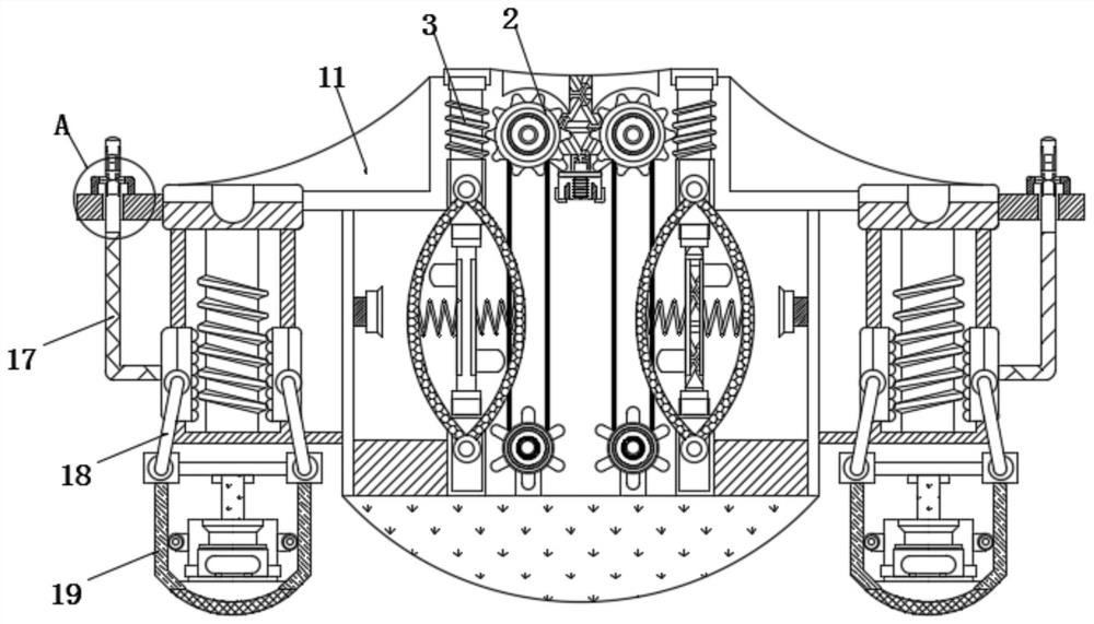
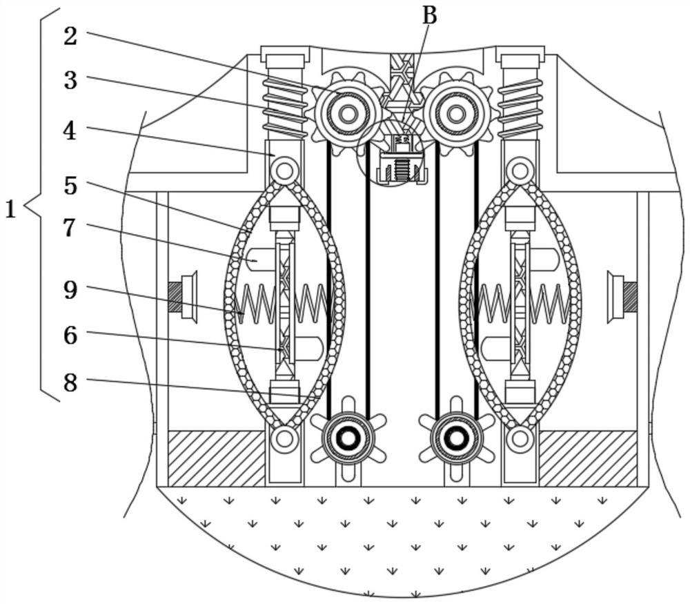
[0027] A collection ship capable of removing cyanobacteria sludge, comprising a drive assembly 1 and an adjustment mechanism 14, the drive assembly 1 includes a driven gear 2, the left side of the driven gear 2 is meshed with a drive shaft 3, and the outside of the drive shaft 3 is sleeved with Positioning pipe 4, the lower surface of driving shaft 3 is fixedly connected with vertical rod 6, the front surface of positioning pipe 4 is fixedly connected with first filter screen 5 and second filter screen 8 respectively from left to right, the left and right sides of vertical rod 6 The two side surfaces are fixedly connected with bump shifting plates 7 , and a tension spring 9 is fixedly connected between the first filter screen 5 and the second filter screen 8 .

[0028] Also comprise positioning assembly 10, positioning assembly 10 comprises cabin frame 11, the left and right sides of cabin frame 11 are positioned at the inside of guide rail bar 15 and are all rotatably connecte...

specific Embodiment 2

[0031] A collection ship capable of removing cyanobacteria sludge, comprising a drive assembly 1 and an adjustment mechanism 14, the drive assembly 1 includes a driven gear 2, the left side of the driven gear 2 is meshed with a drive shaft 3, and the outside of the drive shaft 3 is sleeved with Positioning pipe 4, the lower surface of driving shaft 3 is fixedly connected with vertical rod 6, the front surface of positioning pipe 4 is fixedly connected with first filter screen 5 and second filter screen 8 respectively from left to right, the left and right sides of vertical rod 6 The two side surfaces are fixedly connected with bump shifting plates 7 , and a tension spring 9 is fixedly connected between the first filter screen 5 and the second filter screen 8 .

[0032] The adjustment mechanism 14 includes a guide rail rod 15, the outside of the guide rail rod 15 is sleeved with a sliding cover plate 16, the left side of the sliding cover plate 16 is fixedly connected with a sca...

specific Embodiment 3

[0035] A collection ship capable of removing cyanobacteria sludge, comprising a drive assembly 1 and an adjustment mechanism 14, the drive assembly 1 includes a driven gear 2, the left side of the driven gear 2 is meshed with a drive shaft 3, and the outside of the drive shaft 3 is sleeved with Positioning pipe 4, the lower surface of driving shaft 3 is fixedly connected with vertical rod 6, the front surface of positioning pipe 4 is fixedly connected with first filter screen 5 and second filter screen 8 respectively from left to right, the left and right sides of vertical rod 6 The two side surfaces are fixedly connected with bump shifting plates 7 , and a tension spring 9 is fixedly connected between the first filter screen 5 and the second filter screen 8 .

[0036]Also comprise positioning assembly 10, positioning assembly 10 comprises cabin frame 11, the left and right sides of cabin frame 11 are positioned at the inside of guide rail bar 15 and are all rotatably connected...


PUM


Abstract

The invention relates to the technical field of cyanobacteria sludge collection ships, in particular to a collection ship capable of efficiently removing cyanobacteria sludge, including a drive assembly and an adjustment mechanism, the drive assembly includes a driven gear, and the left side of the driven gear is meshed with a The driving shaft is sleeved with a positioning tube outside, the lower surface of the driving shaft is fixedly connected with a vertical rod, and the front surface of the positioning tube is fixedly connected with the first filter screen and the second filter screen from left to right. The second filter screen, the drive shaft rotates inside the positioning tube, so that the vertical rod at the lower end of the drive shaft drives the bump dial to rotate between the first filter screen and the second filter screen, so that the bump dial pushes the second filter screen back and forth The first filter screen and the second filter screen make the first filter screen and the second filter screen move back and forth, so that the cyanobacteria sludge on the first filter screen and the second filter screen is shaken off, thereby improving the working efficiency of the equipment, so that The equipment efficiently treats cyanobacteria sludge.

Description

technical field [0001] The invention relates to the technical field of cyanobacteria sludge collection ships, in particular to a collection ship capable of removing cyanobacteria sludge. Background technique [0002] Cyanobacteria are the earliest photosynthetic oxygen-evolving organisms. They have played a huge role in changing the earth's surface from an anaerobic atmospheric environment to an aerobic environment. They are widely distributed and spread all over the world. However, most freshwater products, a few marine products, and some cyanobacteria After being polluted by elements such as nitrogen and phosphorus, the "red tide" of seawater and the "bloom" of lakes that cause eutrophication have brought serious harm to fishery and aquaculture. [0003] However, the existing equipment cannot well control the depth of the water pumped into the water, which may affect the absorption and treatment effect of the equipment on the cyanobacteria sludge, and cannot separate the c...

Claims


Application Information

Patent Timeline
Patent Type & Authority Patents(China)
IPC IPC(8): B63B35/32E02B15/10C02F1/00
CPCB63B35/32E02B15/10C02F1/00C02F1/001C02F2201/002C02F2201/004C02F2201/008C02F2303/16C02F2303/14Y02A20/204
Inventor 匡新生赵蓝天
Owner 江西强盛科技有限公司
Why Eureka
Try Eureka