
Energy-saving full-automatic multifunctional arranged biogas digester and working method thereof

A multifunctional biogas digester technology, applied in biochemical equipment and methods, biochemical cleaning devices, enzymatic/microbiological devices, etc., can solve the problems of low gas production and low utilization rate of biogas digesters

Inactive Publication Date: 2021-09-14
陈开银
View PDF0 Cites 2 Cited by
  • Summary
  • Abstract
  • Description
  • Claims
  • Application Information

AI Technical Summary

Problems solved by technology

[0002] In order to realize the emission reduction goals and tasks my country promised to the world at the World Climate Summit, many regions promote the use of biogas as a source of fuel for residents’ daily life and to solve fecal pollution of water sources and the environment. It is more cost-effective and convenient to use electricity or liquefied petroleum gas to obtain other biogas to supplement. The existing biogas digesters have low utilization rate due to low gas production and other reasons. For example, raising 6 pigs to produce biogas can supply 5 People use it normally, and now they only raise 3 pigs. Can we design a biogas digester that increases the gas production by 50%?

Method used


Image

  • Energy-saving full-automatic multifunctional arranged biogas digester and working method thereof
  • Energy-saving full-automatic multifunctional arranged biogas digester and working method thereof
  • Energy-saving full-automatic multifunctional arranged biogas digester and working method thereof

Examples


Embodiment Construction

[0032] In order to make the above features and advantages of the present invention, it can be more easily understood, and the following examples are forth, and the accompanying drawings are described in detail, but the present invention is not limited thereto.

[0033] refer to Figure 1 to 5

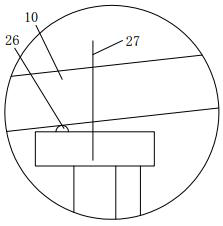
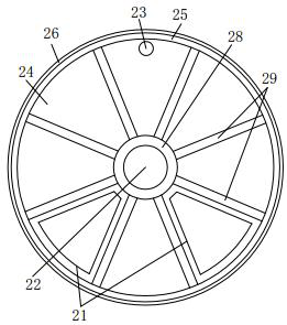
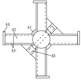
[0034]Setting an energy-saving automatic multi digester, comprising the body 10 lying on the ground, the tank body 20 via a spacer plate between the plurality of partition 11 fermentation to fermentation slurry stepwise. Tank body disposed along the axis direction of a rotating shaft 30 extends through the center of each partition plate, positioned between the central axis of rotation is provided for each of the fermentation are agitated to promote, and the residue embrace pressure slurry agitation impeller 40, the the left end of said body and connected to a pressure between the feed hopper 51 of the cell body 50, provided with a central rotation shaft to the drive mechanism of the automati...


PUM


Abstract

The invention relates to an energy-saving full-automatic multifunctional arranged biogas digester and a working method thereof. The energy-saving full-automatic multifunctional arranged biogas digester comprises a tank body horizontally lying underground, the interior of the tank body is divided into a plurality of fermentation chambers through partition plates, a central rotating shaft penetrating through the partition plates is arranged in the tank body in the axis direction of the tank body, stirring impellers used for stirring, propelling and collecting and pressing biogas slurry and residues are arranged on the central rotating shaft and located in each fermentation chamber, the left end of the tank body is connected with a digester body with a water pressure room serving as a feeding port, an automatic feeding driving mechanism is arranged on the digester body, an automatic residue discharging mechanism is arranged at the right end of the tank body, and a biogas storage and output mechanism is arranged at the upper part of the tank body; and the central rotating shaft, the driving mechanism and the automatic residue discharging mechanism are operated by an automatic cycle time relay to operate a motor for several times every day to complete the whole implementation process. According to the biogas digester, nutrients in the biogas slurry can be fully utilized and converted into biogas, and the gas production rate is increased by about 50%.

Description

Technical field [0001] The present invention relates to an energy-saving automatic multi disposed digesters and working methods. Background technique [0002] To achieve our commitment to the World Climate Summit reduction targets and tasks to the world in many areas to promote the use of biogas as a fuel source for residents in their daily lives and solve faecal contamination of water, the environment, but because raising livestock manure biogas little less inadequate material, if high-wage workers spend marsh to obtain additional material to supplement, rather that the liquefied gas or electricity more cost-effective and convenient, since conventional digesters low gas production reasons, the utilization rate is not high, such as raising 6 pigs manure for biogas production 5 normal people use, it is raised only three can be designed to improve the yield if 50% of the digester gas to solve, which is the original intention of the present application, and therefore a need for an e...

Claims


Application Information

Patent Timeline
IPC IPC(8): C12M1/107C12M1/02C12M1/36C12M1/34C12M1/00
CPCC12M21/04C12M23/18C12M45/02C12M23/34C12M39/00C12M41/48C12M41/34
Inventor 陈开银
Owner 陈开银
Learn More