Building construction concrete spraying unit with protection mechanism

A technology of concrete injection unit and building construction, which is applied in the direction of construction, building structure, and construction material processing, etc., and can solve the problems of unfavorable operation efficiency, poor use effect of concrete injection unit, easy blockage of pipelines, etc.

Inactive Publication Date: 2021-09-14
PINGMEI SHENMA CONSTR ENG GROUP
View PDF9 Cites 0 Cited by
  • Summary
  • Abstract
  • Description
  • Claims
  • Application Information

AI Technical Summary

Problems solved by technology

[0005] The object of the present invention is to provide a concrete spraying unit for building construction with a protective mechanism, which can stir the internal concrete through the stirring rod and the spiral stirring shaft, so as to prevent the internal concrete from solidifying, which is helpful for the conveying and spraying of materials, through The ejector rod and the hinged seat can adjust the spraying angle of the delivery pipe, which is convenient for spraying at different angles according to the needs. The first spraying pipe and the second spraying pipe are used as spares for each other, so there is no need to stop temporarily to clear the first spraying pipe. It ensures the continuous spraying operation and significantly improves the use effect and efficiency of the concrete spraying unit. By setting the anti-blocking component, it can effectively clean the inside of the conveying pipe, prevent the inside of the conveying pipe from clogging, and improve the protection of the concrete spraying unit. Effect and the o

Method used


Image

  • Building construction concrete spraying unit with protection mechanism
  • Building construction concrete spraying unit with protection mechanism
  • Building construction concrete spraying unit with protection mechanism

Examples


Embodiment 1

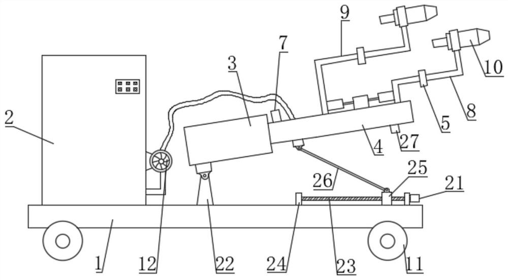
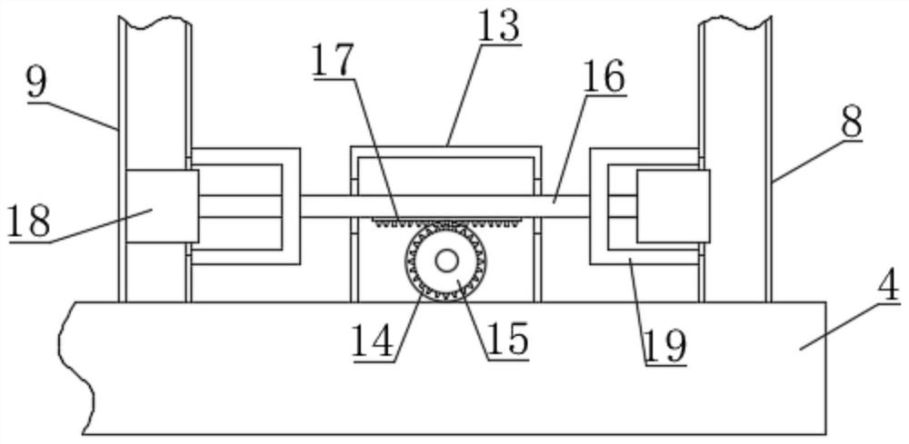
[0041] Such as Figure 1-8 As shown, a concrete injection unit for building construction with a protective mechanism proposed by the present invention includes a base plate 1, a material storage box 2, a delivery pipe 4, a roller 11 and a feed pump 12, and the bottom of the base plate 1 is installed with multiple sets of The roller 11 and the material storage box 2 are fixedly installed on the top of the bottom plate 1 by bolts, and the material storage box 2 is equipped with a material delivery pump 12, which transports the concrete in the material storage box 2 to the delivery pipe 4, and the material storage An air pump or an air compressor is also installed on the box 2, and the delivery pipe 4 is located above the bottom plate 1 and connected to the fixed box 3. An anti-blocking component 6 for cleaning the inside of the delivery pipe 4 is installed in the fixed box 3. On the delivery pipe 4, The first spray pipe 8 and the second spray pipe 9 are installed, the end of the...

Embodiment 2

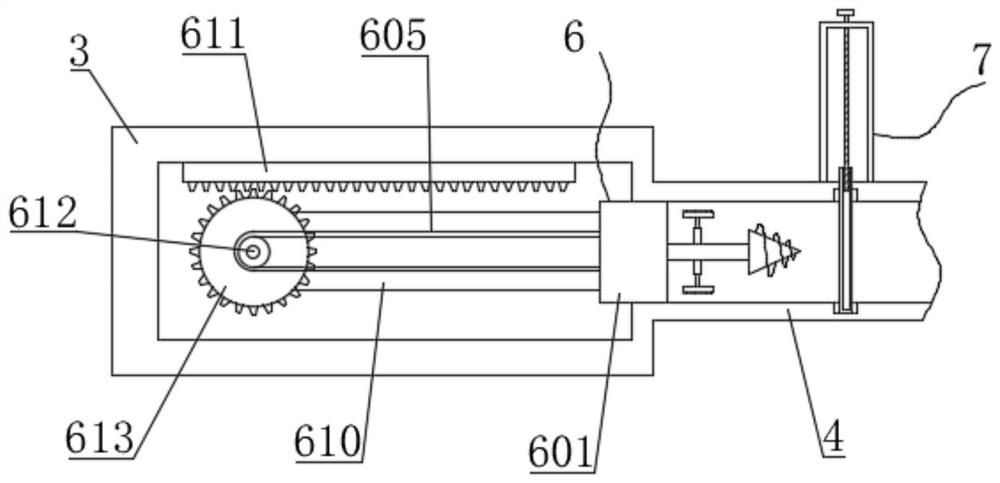
[0047] Such as image 3 and Figure 9As shown, the difference between this embodiment and Embodiment 1 is that a sealing assembly 7 is installed on the delivery pipe 4, the sealing assembly 7 and the anti-blocking assembly 6 are located on the same side, and the sealing assembly 7 includes a hollow plate 701, a screw 702, a knob 703, Sealing plate 704, thread groove 705 and draw-in groove 706, hollow plate 701 is vertically arranged on the top of delivery pipe 4, screw rod 702 is installed in hollow plate 701 by bearing rotation, knob 703 is arranged on the top of screw rod 702 and is positioned at hollow plate 701 Turn the knob 703 to make the screw 702 rotate, the sealing plate 704 is vertically provided with an upward threaded groove 705, the screw 702 is threadedly connected with the sealing plate 704, and the inner wall of the bottom of the delivery pipe 4 is provided with a card with an upward opening. slot 706, and the sealing plate 704 is inserted downwards into the c...

Embodiment 3

[0049] Such as Figure 10 As shown, the difference between this embodiment and Embodiment 1 and Embodiment 2 is that the material storage box 2 includes a box body 201, a first motor 202, a rotating shaft 203, a stirring rod 204, a sealing box 205 and a spiral stirring shaft 206, and the box The body 201 is fixedly installed on the top of the base plate 1 by bolts, the first motor 202 is fixedly installed on the top of the box body 201 through the motor base, the output end of the first motor 202 is connected with the rotating shaft 203, and the first motor 202 is used to drive the rotating shaft 203, a plurality of groups of stirring rods 204 are arranged horizontally and are connected with the rotating shaft 203. When the rotating shaft 203 rotates, each group of stirring rods 204 rotates in a horizontal direction to stir the concrete in the box body 201 to prevent The inner concrete is solidified; the inner wall of the bottom of the box body 201 is fixedly equipped with a s...


PUM


Abstract

The invention belongs to the technical field of building construction equipment, and particularly relates to a building construction concrete spraying unit with a protection mechanism. The building construction concrete spraying unit with a protection mechanism aims at solving the problems that a pipeline of an existing concrete spraying unit is prone to blockage, the protection effect is poor, the use effect of the concrete spraying unit is poor, and when a spraying pipe is blocked, the concrete spraying unit needs to be shut down and unblocked, and use is not facilitated. The building construction concrete spraying unit with the protection mechanism comprises a bottom plate; a conveying pipe is located above the bottom plate and is connected with a fixed box; an anti-blocking assembly is installed in the fixed box; a first spraying pipe and a second spraying pipe are installed on the conveying pipe; spraying heads are installed at the tail ends of the first spraying pipe and the second spraying pipe; and a cleaning assembly is mounted on each spraying head. According to the concrete spraying unit, the interior of the conveying pipe is cleaned through the anti-blocking assembly, blockages blocked in the spraying pipes are loosened through a vibration assembly, materials in the spraying heads are removed through the cleaning assemblies, the first spraying pipe and the second spraying pipe are standby for each other, and the protection effect and the use effect of the concrete spraying unit are improved.

Description

technical field [0001] The invention relates to the technical field of building construction equipment, in particular to a concrete injection unit for building construction with a protective mechanism. Background technique [0002] The concrete spraying unit is the concrete spraying machine, which uses compressed air to continuously transport the concrete along the pipeline and spray it onto the construction surface. It can be divided into two categories: dry spraying machine and wet spraying machine. It is sprayed out after mixing with pressure water at the nozzle, and the latter is conveyed by pneumatic or concrete pump to spray out the concrete mixture through the nozzle, which is widely used in the lining construction of underground engineering, shafts, tunnels, culverts, etc.; [0003] In the Chinese patent application number 2019221111464, a construction concrete sprayer is disclosed, including a bottom plate, a mixing box is fixedly connected to the middle of the top ...

Claims


Application Information

Patent Timeline
IPC IPC(8): E04G21/02E04G21/04B08B9/032B08B9/053B08B9/043B08B9/047B28C5/08B28C5/14B28C5/16
CPCE04G21/02E04G21/04E04G21/0436E04G21/0418B08B9/032B08B9/053B08B9/043B08B9/0433B08B9/047B28C5/16B28C5/0806B28C5/142
Inventor 王海龙张亮朱小青董勤良沈朝营臧江涛耿方方郭爱东郑瑛瑛赵瑞磊曹辉辉潘士强朱永辉邵要锋王蓓
Owner PINGMEI SHENMA CONSTR ENG GROUP
Why Eureka
Try Eureka