
Double-cylinder type vacuum pump

A double-cylinder, vacuum pump technology, applied in variable capacity pump components, pumps, pump control, etc., can solve the problems of high manufacturing and use costs, poor use effect, poor pumping effect, etc.

Pending Publication Date: 2021-09-14
顾亚辉
View PDF7 Cites 0 Cited by
  • Summary
  • Abstract
  • Description
  • Claims
  • Application Information

AI Technical Summary

Problems solved by technology

[0004] The above-mentioned double-cylinder vacuum pump has the following disadvantages: the piston is driven to reciprocate and vacuumize through the deformation of the two-way shape memory metal strip, and the pulling force or thrust generated when the two-way shape memory metal strip is deformed is small, so When the two-way shape memory metal strip is deformed, it can only drive the piston to move in a small range and at a slow moving rate, resulting in a slow pumping rate and poor pumping effect of the vacuum pump. When the pressure in the pumped container is small, the piston will be It is sucked tightly on one end of the cylinder and cannot continue to move, which will cause the vacuum pump to be unable to continue to pump out the air in the container, and the work stability is poor. Moreover, the first pressure sensor, the second pressure sensor, the control device and the solenoid valve work together to drive the double pressure sensor. The shape memory metal strip drives the piston to move back and forth, the structure is complex, the manufacturing and use costs are high, the failure rate is high, and the use effect is poor

Method used


Image

  • Double-cylinder type vacuum pump
  • Double-cylinder type vacuum pump
  • Double-cylinder type vacuum pump

Examples


Embodiment Construction

[0033] The following will clearly and completely describe the technical solutions in the embodiments of the present invention with reference to the accompanying drawings in the embodiments of the present invention. Obviously, the described embodiments are only some, not all, embodiments of the present invention. Based on the embodiments of the present invention, all other embodiments obtained by persons of ordinary skill in the art without making creative efforts belong to the protection scope of the present invention.

[0034] In describing the present invention, it is to be understood that the terms "center", "longitudinal", "transverse", "length", "width", "thickness", "upper", "lower", "front", " Back", "Left", "Right", "Straight", "Horizontal", "Top", "Bottom", "Inner", "Outer", "Clockwise", "Counterclockwise", etc. or The positional relationship is based on the orientation or positional relationship shown in the drawings, which is only for the convenience of describing t...


PUM


Abstract

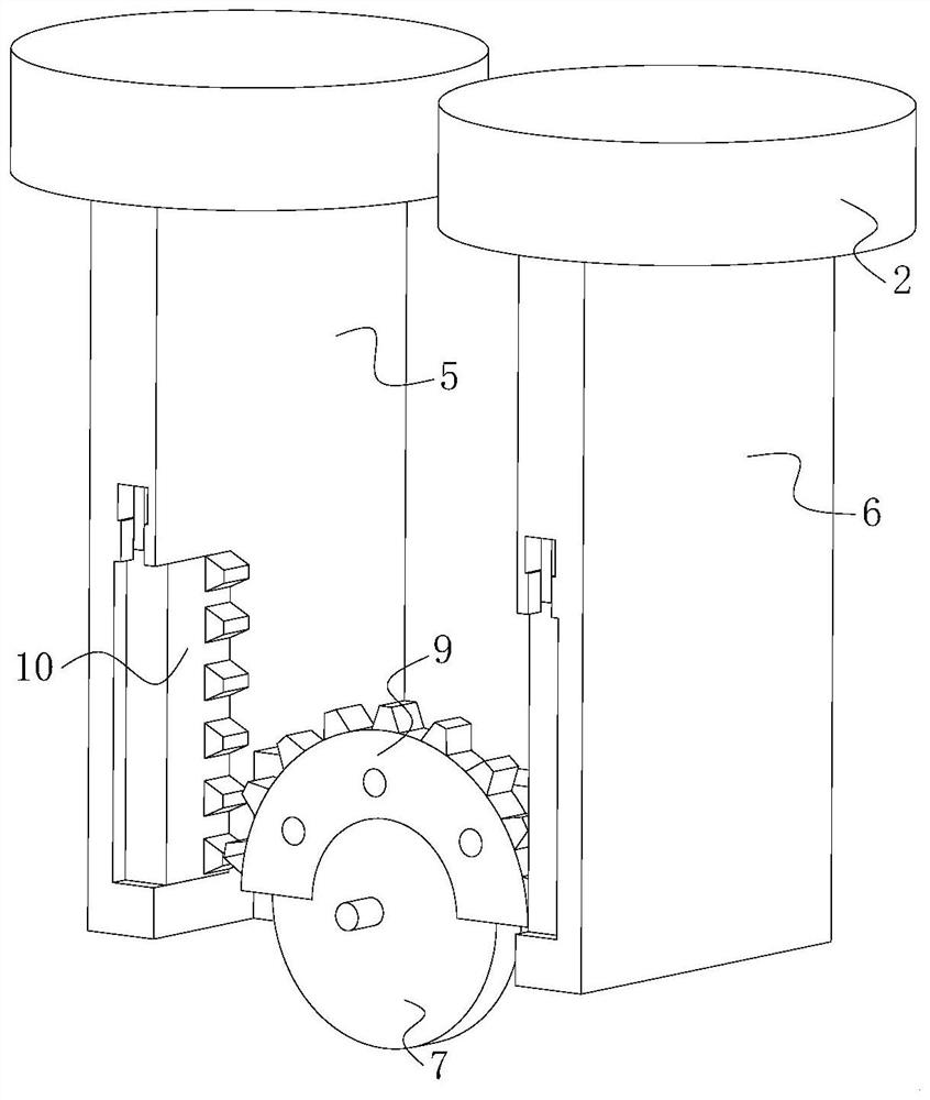
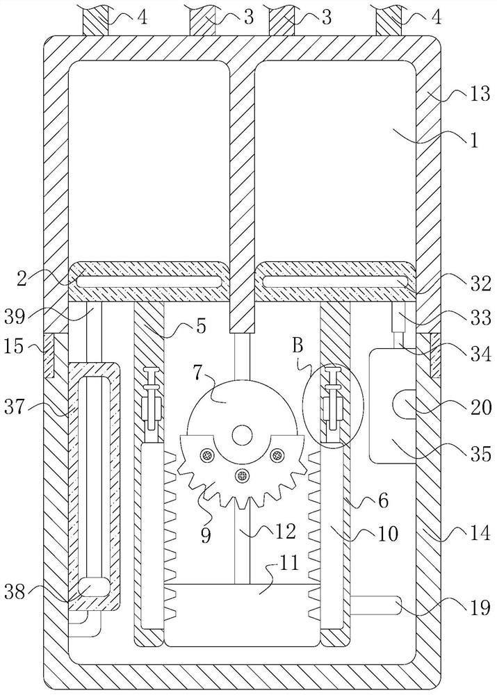
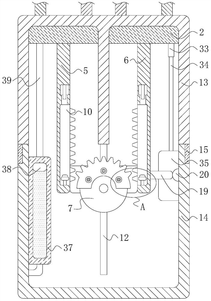
The invention relates to the technical field of vacuum pumps, and particularly relates to a double-cylinder type vacuum pump. The double-cylinder type vacuum pump comprises a pump body and two cylinders symmetrically arranged in the pump body, wherein pistons are mounted in the two cylinders; an exhaust pipe and an exhaust pipe are mounted at one end of each of the two cylinders; a first mounting plate and a second mounting plate are mounted at the ends, far away from the exhaust pipes, of the two pistons respectively; a rotating disc is rotationally mounted in the pump body and located between the first mounting plate and the second mounting plate; a driving motor is connected onto the rotating disc; and a transmission mechanism is arranged between the rotating disc and the first mounting plate as well as between the rotating disc and the second mounting plate. The two pistons can be driven to reciprocate by the one-way driving motor with a simple structure, the vacuumizing function of the vacuum pump is realized, devices such as a sensor, a control device, an electromagnetic valve and the like are not required to be used, the structure is simple, the manufacturing and use cost of the vacuum pump is reduced, the failure rate of the vacuum pump is remarkably reduced, and the use effect of the vacuum pump is improved.

Description

technical field [0001] The invention relates to the technical field of vacuum pumps, in particular to a double-cylinder vacuum pump. Background technique [0002] A vacuum pump refers to a device or device that uses mechanical, physical, chemical or physicochemical methods to pump air into a pumped container to obtain a vacuum. Generally speaking, a vacuum pump uses various methods to improve, generate and maintain a vacuum in a closed space. Vacuum device. [0003] After retrieval, Chinese Patent No. CN110374840B discloses a double-cylinder vacuum pump, including a first cylinder, a second cylinder and a heat-conducting cover plate, the first cylinder and the second cylinder are arranged side by side, and the first cylinder and the second cylinder Pistons, guiding telescopic rods, and two-way shape-memory metal strips with acute-angled high-temperature phases and I-shaped low-temperature phases are installed in the two cylinders. Both the first cylinder and the second cyli...

Claims


Application Information

Patent Timeline
Patent Type & Authority Applications(China)
IPC IPC(8): F04B27/00F04B37/14F04B35/04F04B39/00F04B49/10F04B39/06
CPCF04B27/005F04B37/14F04B35/04F04B39/0022F04B49/10F04B39/06
Inventor 顾亚辉许智勇
Owner 顾亚辉
Learn More