Clamp for impact tensile fatigue test of round bar test piece
A fatigue test and test piece technology, applied in the direction of measuring devices, instruments, scientific instruments, etc.
- Summary
- Abstract
- Description
- Claims
- Application Information
AI Technical Summary
Problems solved by technology
Method used
Image
Examples
Embodiment Construction
[0017] The present invention will be described in detail below with the drop weight impact testing machine as the impact driving device and in conjunction with the accompanying drawings.
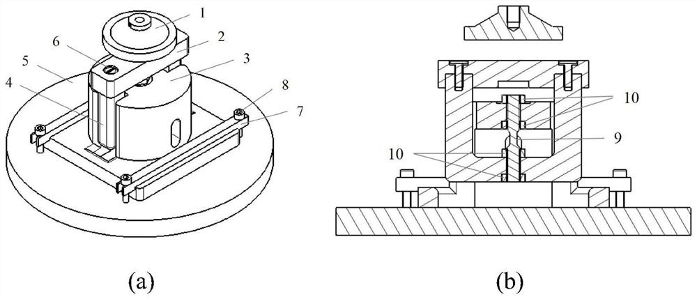
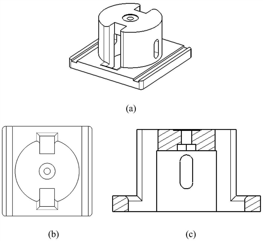
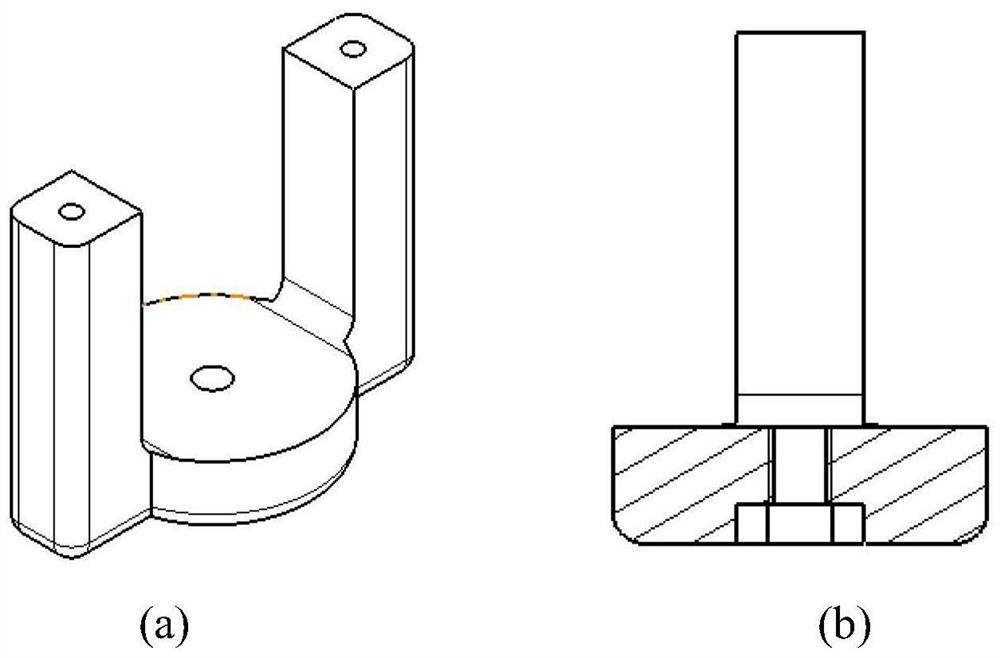
[0018] as attached figure 1 As shown, the present invention is mainly designed for the metal material impact tensile fatigue test fixture, and the fixture includes a hammer head 1, a connecting cover plate 2, a support 3, a lower chuck 4, a base 5, a connecting screw 6, a bead 7, an adjustment Screw 8, test piece 9, lock nut 10. The hammer head 1 is connected to the plunger of the drop weight impact testing machine, and the base is connected to the base of the testing machine. The lower clamping section of the test piece is connected to the lower chuck through thread fit and double nuts, and the upper clamping section of the test piece is connected through double locking. The nut is connected to the upper end of the support. At this time, the lower chuck is located in the inner cavity of th...
PUM
| Property | Measurement | Unit |
|---|---|---|
| Diameter | aaaaa | aaaaa |
Abstract
Description
Claims
Application Information
 - R&D
- Intellectual Property
- Life Sciences
- Materials
- Tech Scout
- Unparalleled Data Quality
- Higher Quality Content
- 60% Fewer Hallucinations
Browse by: Latest US Patents, China's latest patents, Technical Efficacy Thesaurus, Application Domain, Technology Topic, Popular Technical Reports.
© 2025 PatSnap. All rights reserved.Legal|Privacy policy|Modern Slavery Act Transparency Statement|Sitemap|About US| Contact US: help@patsnap.com


