
High-voltage electrostatic coating equipment for new energy automobile

A new energy vehicle, high-voltage electrostatic technology, applied in the direction of liquid spraying equipment, electrostatic spraying device, spraying electric energy device, etc., can solve the problems of affecting the quality of workpieces, uneven spraying, waste of materials, etc., and achieve good spraying effect and high spraying accuracy Effect

Active Publication Date: 2021-09-17
南通普菲特涂装有限公司
View PDF7 Cites 0 Cited by
  • Summary
  • Abstract
  • Description
  • Claims
  • Application Information

AI Technical Summary

Problems solved by technology

[0003] In order to reduce the workload of the personnel, the spray gun originally held by the personnel is fixed on the bracket, and the start and stop of the spray gun are controlled through the cooperation of the sensor and the integrated control system. When the existing device is spraying, the spray gun is fixed on the bracket and can spray straight panels. However, when spraying curved new energy vehicle parts, it is necessary to adjust the angle of the spray gun multiple times, or use multiple stations for spraying. Since the spraying is not completed at one time, when changing the spraying station or adjusting the angle of the spray gun , prone to uneven spraying, resulting in waste of materials and affecting the quality of the workpiece

Method used


Image

  • High-voltage electrostatic coating equipment for new energy automobile
  • High-voltage electrostatic coating equipment for new energy automobile
  • High-voltage electrostatic coating equipment for new energy automobile

Examples


Embodiment Construction

[0024] Embodiments of the present patent are described in detail below, examples of which are shown in the drawings, wherein the same or similar reference numerals designate the same or similar elements or elements having the same or similar functions throughout. The embodiments described below by referring to the figures are exemplary and are only used for explaining the patent, and should not be construed as limiting the patent.

[0025] In the description of this patent, it is to be understood that the terms "center", "upper", "lower", "front", "rear", "left", "right", "vertical", "horizontal", The orientation or positional relationship indicated by "top", "bottom", "inner", "outer", etc. is based on the orientation or positional relationship shown in the drawings, and is only for the convenience of describing this patent and simplifying the description, rather than indicating or implying References to devices or elements must have a particular orientation, be constructed, ...


PUM


Abstract

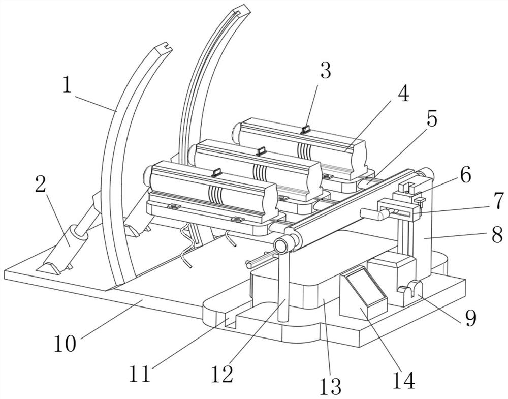
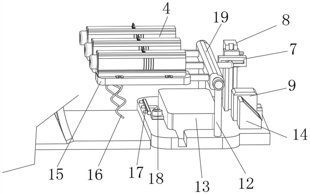
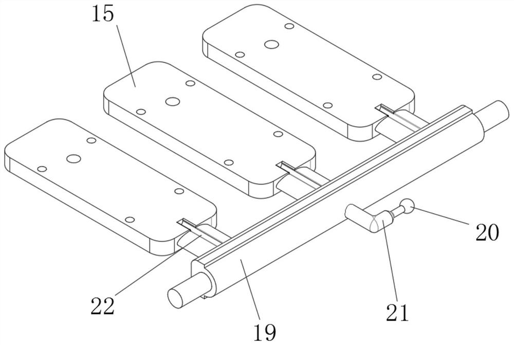
The invention discloses high-voltage electrostatic coating equipment for a new energy automobile. The high-voltage electrostatic coating equipment for the new energy automobile comprises a central controller, a voltage transformation and stabilization device and a bottom plate; a coating tank and a discharging pump are arranged on the bottom plate, the feeding end of the discharging pump penetrates through the coating tank and extends into the coating tank, and a discharging pipe is fixedly installed at an output port of the discharging pump; and a guide rail and two symmetrically-distributed supporting columns are arranged on the outer wall of the top of the bottom plate, a reinforcing rod is rotationally connected between the two supporting columns through bearings, a corner rod is arranged on the outer wall of one side of the reinforcing rod, and a rotating ball is arranged at one end of the corner rod. According to the high-voltage electrostatic coating equipment for the new energy automobile, chain plates are kept in a bent arc shape, then a linear motor is started, the linear motor drives a moving block to move up and down in the up-down moving process, the reinforcing rod is made to rotate with the supporting columns as supports, spray gun bodies installed on mounting plates are driven to rotate, the moving track of the spray gun bodies is in an arc shape, and therefore curved surface spraying is achieved; and as the linear motor is high in precision, the spraying precision is high, and the spraying effect is good.

Description

technical field [0001] The invention relates to the technical field of electrostatic spraying, in particular to a high-voltage electrostatic coating equipment for new energy vehicles. Background technique [0002] High-voltage electrostatic spraying mainly uses a corona discharge electrostatic powder spray gun system to complete powder spraying. The system mainly includes: a high-voltage electrostatic generator, which is composed of a high-frequency transformer and a boost circuit; a corona discharge electrode, which is composed of a needle electrode and a ring electrode; a spray regulator; air and powder conveying pipelines. With the continuous development and innovation of spraying technology, it is now possible to install a high-voltage electrostatic generator inside the spray gun. Turn on the low-voltage power supply, convert it into high-voltage electricity through a multi-stage booster, and apply it to the corona discharge electrode or ring electrode at the end of the...

Claims


Application Information

Patent Timeline
IPC IPC(8): B05B5/08B05B5/053B05B13/04
CPCB05B5/082B05B5/081B05B5/053B05B13/04
Inventor 杨本志徐素兵张连琴徐皓玥张徐浩朱齐跃王玉蓉朱家禾蔡卫东王海峰
Owner 南通普菲特涂装有限公司
Learn More