U-shaped steel plate bending machine

A bending machine and steel plate technology, applied in the field of steel plate processing, can solve the problems of scratching the steel plate, unable to clean the steel plate, increasing the manufacturing cost of the steel plate, etc., to prevent the adhesion of impurities and dust, ensure the implementation effect, and ensure the effect of cleanliness.

Active Publication Date: 2021-09-17
山东汇创材料科技有限公司
View PDF13 Cites 1 Cited by
  • Summary
  • Abstract
  • Description
  • Claims
  • Application Information

AI Technical Summary

Problems solved by technology

[0002] The steel plate bending machine is an important equipment for bending and forming workpieces in the sheet metal industry. Its function is to press the steel plate into parts of various shapes according to the process requirements; among them, the U-shaped steel plate bending machine bends the steel plate into a U shape; The use environment of the steel plate bending machine is in the factory workshop; the staff cuts the steel plate of the required bending size from a whole steel plate, and the impurities and burrs on the edge of the steel plate produced by the staff when cutting the steel plate will splash on the surface of the steel plate , so that when the steel plate is bent, these impurities will scratch the surface of the steel plate; thus, the steel plate with high requirements for processing accuracy and surface smoothness cannot meet the required requirements after bending; thus making the steel plate scrap or need to be reworked and polished, Cause unnecessary waste and increase the manufacturing cost of the steel plate
[0003] For example, a Chinese patent with the application number CN201922072684.7 discloses a bending machine for U-shaped steel plate processing, including a frame, an oil cylinder and an upper platen, the oil cylinder is fixedly installed above the frame of the bending machine, and the The upper pressing plate is fixedly connected with the piston rod of the oil cylinder, and two connecting plates distributed at intervals are fixedly installed under the upper pressing plate, and the upper mold is fixedly connected with the upper pressing plate through the connecting plate; The connecting plate can avoid the height of the U-shaped steel plate during the bending process of the bending machine, effectively avoiding the collision between the edge of the U-shaped steel plate and the upper platen of the bending machine, which can make the U-shaped steel plate safe to form The damage to the bending machine is well avoided, the design is reasonable, and the practicability is strong; however, this technical solution cannot clean the surface of the steel plate during use, so that the impurities on the surface of the steel plate will scratch the steel plate when the steel plate is bent, thus The quality of the steel plate cannot meet the requirements, which in turn causes the limitation of the scheme

Method used


Image

  • U-shaped steel plate bending machine
  • U-shaped steel plate bending machine
  • U-shaped steel plate bending machine

Examples


Embodiment approach

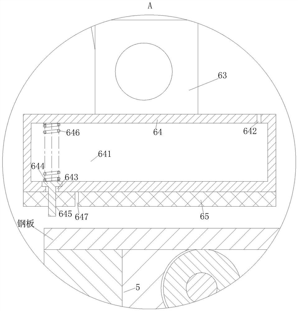
[0040] As an embodiment of the present invention, the step hole 643, the push rod 644, the through hole 645 and the return spring 646 are arranged away from the support plate 3; the end surface of the cleaning layer 65 away from the cleaning strip 64 is provided with a cutting groove 647; The cutting groove 647 runs through the cleaning layer 65, and the cutting groove 647 is arranged close to the through hole 645. The cutting groove 647 divides the cleaning layer 65 into two parts that are close to and far from the support plate 3;

[0041] During work, along with the decline of the position of the cleaning strip 64, the push rod 644 in the cleaning strip 64 is jacked up, so that the lubricating oil in the cavity 641 penetrates into the cleaning layer 65 away from the support plate 3 through the step hole 643; After the cleaning layer 65 of the plate 3 cleans the surface of the steel plate, the cleaning layer 65 away from the support plate 3 brushes the lubricating oil on the ...


PUM


Abstract

The invention relates to the technical field of steel plate machining, in particular to a U-shaped steel plate bending machine. The U-shaped steel plate bending machine comprises an upper rack; a lower mold is arranged on the lower rack; an upper mold is arranged on the upper rack; fixing plates are arranged on the two sides of the upper mold; the other end of the hinge rod is hinged to a hinge block; a cleaning layer is arranged on the end surface, close to the steel plate, of a cleaning strip; and a steel rope is arranged between a fixing plate and the corresponding hinge rod. According to the U-shaped steel plate bending machine, the upper mold drives the fixing plate to move downwards together, and then the fixing plate drives the hinge rod to move and the hinge rod drives the cleaning strip to move, so that when the upper mold moves downwards, the purpose that the cleaning block and the cleaning layer slide on the steel plate in the direction close to the supporting plate is achieved, so that impurities and dust on the surface of the steel plate are wiped away by the cleaning layer, the cleanliness of the surface of the steel plate is guaranteed, and therefore the steel plate cannot be scratched by the impurities and the dust when the steel plate is pressed into the lower die by the upper mold, and the quality of the steel plate cannot be affected.

Description

technical field [0001] The invention relates to the technical field of steel plate processing, in particular to a U-shaped steel plate bending machine. Background technique [0002] The steel plate bending machine is an important equipment for bending and forming workpieces in the sheet metal industry. Its function is to press the steel plate into parts of various shapes according to the process requirements; among them, the U-shaped steel plate bending machine bends the steel plate into a U shape; The use environment of the steel plate bending machine is in the factory workshop; the staff cuts the steel plate of the required bending size from a whole steel plate, and the impurities and burrs on the edge of the steel plate produced by the staff when cutting the steel plate will splash on the surface of the steel plate , so that when the steel plate is bent, these impurities will scratch the surface of the steel plate; thus, the steel plate with high requirements for processi...

Claims


Application Information

Patent Timeline
Patent Type & Authority Applications(China)
IPC IPC(8): B21D5/02B08B1/00B21D37/18
CPCB21D5/02B21D5/0209B08B1/008B21D37/18Y02P70/10
Inventor 陈保强卜东平
Owner 山东汇创材料科技有限公司
Why Eureka
Try Eureka