Error sensing compensation method for precision machining

A technology of precision machining and compensation method, applied in the direction of metal processing, metal processing equipment, metal processing mechanical parts, etc., can solve the problem of no sensor function, achieve the effect of improving processing accuracy, solving precision machining of machine tools, and achieving continuity

Active Publication Date: 2021-09-17
NANJING LINGJI YIDONG DRIVING TECH CO LTD
View PDF7 Cites 2 Cited by
  • Summary
  • Abstract
  • Description
  • Claims
  • Application Information

AI Technical Summary

Problems solved by technology

At present, in the design of intelligent material actuators at home and abroad, the intelligent material is basically used as the driving body, and a kind of intelligent material is used for design, and it only drives without sensing function.

Method used


Image

  • Error sensing compensation method for precision machining
  • Error sensing compensation method for precision machining
  • Error sensing compensation method for precision machining

Examples


Embodiment 1

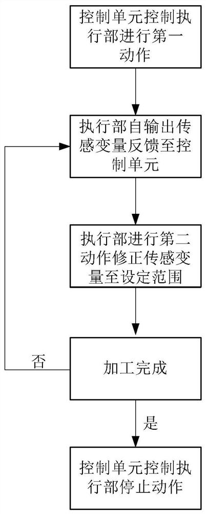
[0047] The invention provides an error sensing compensation method for precision machining, comprising the following steps:

[0048] S1: the control unit receives the processing instruction and outputs the first control command to control the executing part to perform the first action;

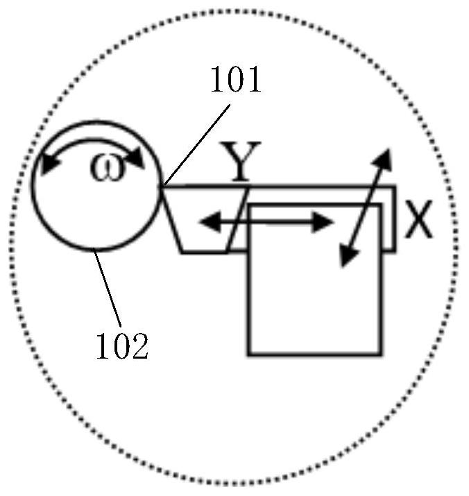
[0049] S2: During the action of the executing part, the sensing variable is self-output and the sensing variable is fed back to the control unit. The detection part of the sensing variable comes from the tool tip 101 of the tool of the executing part. The sensing variable is obtained by changing the frequency parameter.

[0050] S3: The control unit outputs the second control command to control the execution part to perform the second action, thereby correcting the sensing variable to the set range, and performing feedback and command output in real time, so that the correction of the processing sensing variable is performed in real time, thereby ensuring that the workpiece 102 machining accu...

Embodiment 2

[0066] This embodiment is a preferred example of Embodiment 1.

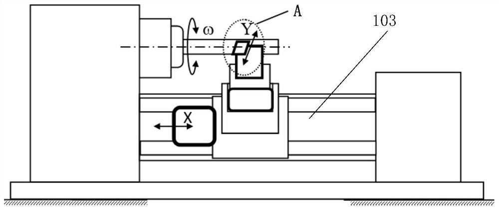
[0067] In this embodiment, a lathe is taken as an example to describe a method for implementing error sensor compensation in the machining process of the machine tool 103 . In addition, the tool in the present invention is any one or more of piezoelectric material bodies, magnetostrictive material bodies, electromagnetic permanent magnet material bodies, shape memory alloy material bodies, electrostatic material bodies, and phase change material bodies in series. A combination of different material bodies, wherein a multi-body combination comprising the same material body, can also achieve the effects of the present invention through the arrangement of structures. Specifically, the cutting tool includes the use of materials with applied magnetic field or electric field, cold and hot deformation, fluid pressure deformation, and chemical reaction deformation, which can realize signal acquisition and then realize se...


PUM


Abstract

The invention provides an error sensing compensation method for precision machining. The error sensing compensation method comprises the following steps that S1, a control unit receives a machining instruction and outputs a first control command to control an execution part to perform a first action; S2, the execution part automatically outputs a sensing variable in the action process and feeds back the sensing variable to the control unit; S3, the control unit outputs a second control command to control the execution part to perform a second action so as to correct the sensing variable to a set range; S4, if machining is continued, a system returns to S2; and if machining is completed, the control unit controls the execution part to stop acting. According to the method, force and / or displacement adjustment of a tool nose and a workpiece is finally realized through self-sensing and self-driving of a tool according to various complex factors influencing the machining precision, so that accurate error compensation is realized, the final machining precision is further realized, the complex problem is simplified, and the machining precision is greatly improved.

Description

technical field [0001] The invention relates to the technical field of machining, in particular to an error sensing compensation method for precision machining. Background technique [0002] During machining, the machine tool drives the tool to move relative to the workpiece, and then completes the surface processing of the workpiece. The amount of removal or addition in the machining process is the certainty of the processing size, and the relative displacement between the executing part (machine tool, 3D printing nozzle space position feed position) and the executed part (workpiece or 3D printing workpiece) Or the feed rate of the machine tool is in a corresponding relationship. All kinds of processing machine tools are related to the executing part and the executed part, whether removing material or adding material. The dimensional accuracy and surface quality of the executed part depend on the real-time stability and controllability of the relative position and relativ...

Claims


Application Information

Patent Timeline
Patent Type & Authority Applications(China)
IPC IPC(8): B23Q15/12
CPCB23Q15/12
Inventor 杨斌堂
Owner NANJING LINGJI YIDONG DRIVING TECH CO LTD
Why Eureka
Try Eureka