Modular reducing pipeline inner plugging device, driving mechanism and coordination ring
A technology of driving mechanism and occluder, which is applied in the direction of pipe components, mechanical equipment, pipes/pipe joints/fittings, etc. It can solve the difficult plugging operation of large-diameter and high-pressure pipelines, and the internal occluder cannot complete the plugging task , the radius of the internal occluder is very strict, etc., to achieve good passability and plugging adaptability, high plugging pressure, and improved load distribution
- Summary
- Abstract
- Description
- Claims
- Application Information
AI Technical Summary
Problems solved by technology
Method used
Image

Examples
Embodiment 1
[0067] see Figure 1 to Figure 14 , the present invention provides a technical solution:
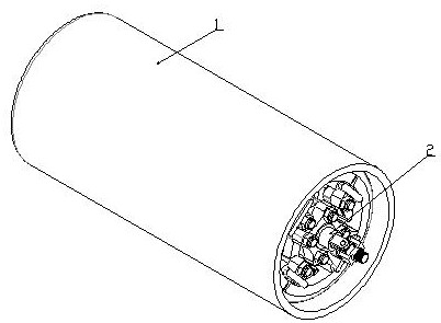
[0068] Such as figure 1 , figure 2 As shown, it is a schematic diagram of the overall structure layout of the present invention. A modular variable-diameter pipeline internal occluder of the present invention mainly includes two parts: a sealing barrel 1 and a pressing mechanism 2; the sealing barrel 1 is a deformable Made of rubber material, its structure is a cylindrical barrel-shaped structure with one end open;
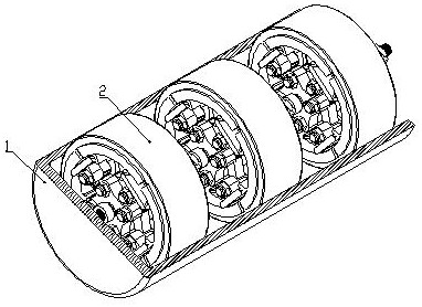
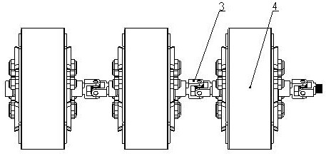
[0069] Such as figure 2 , image 3 As shown, it is a schematic diagram of the structural layout of the pressing mechanism of the present invention. The pressing mechanism 2 is a deformable serial structure connected by a plurality of variable diameter modules 4 through universal joints 3, which is installed inside the sealed barrel 1 to seal During the operation, the sealing barrel 1 can be pressed tightly on the inner wall of the pipeline through each variable diamet...
Embodiment 2
[0079] see Figure 1 to Figure 14 , the present invention provides a technical solution:
[0080] Such as figure 1 , figure 2 As shown, it is a schematic diagram of the overall structure layout of the present invention. A modular variable-diameter pipeline internal occluder of the present invention mainly includes two parts: a sealing barrel 1 and a pressing mechanism 2; the sealing barrel 1 is a deformable Made of rubber material, its structure is a cylindrical barrel-shaped structure with one end open;
[0081] Such as figure 2 , image 3 As shown, it is a schematic diagram of the structural layout of the pressing mechanism of the present invention. The pressing mechanism 2 is a deformable serial structure connected by a plurality of variable diameter modules 4 through universal joints 3, which is installed inside the sealed barrel 1 to seal During the operation, the sealing barrel 1 can be pressed tightly on the inner wall of the pipeline through each variable diamet...
PUM
 Abstract
Description
Claims
Application Information