Eureka AIR delivers breakthrough ideas for toughest innovation challenges, trusted by R&D personnel around the world.

Discrete atmosphere laser radar system based on imaging principle

A technology based on laser radar and imaging principles, applied in radio wave measurement systems, climate sustainability, electromagnetic wave re-radiation, etc., can solve problems such as difficult disassembly, large volume, and complex adjustment, and achieve compact structure, small volume, and convenience Effects of removal and replacement

Pending Publication Date: 2021-09-17
DALIAN UNIV OF TECH
View PDF0 Cites 0 Cited by
  • Summary
  • Abstract
  • Description
  • Claims
  • Application Information

AI Technical Summary

Problems solved by technology

At present, atmospheric aerosol lidar generally has problems such as large size, complicated adjustment, and difficulty in portability and movement. The receiving telescope installed in the lidar system is relatively large in size, and the telescope is fixed in the lidar system and is not easy to disassemble; The divergence angle of the laser beam emitted by the laser in the laser needs to match the acceptance angle of the lens, so the laser radar system has a distance requirement for the optical path of the laser emitted by the laser, and the components that make up the laser radar system are fixed inside the radar system. The lidar for sol detection is bulky, and it is not convenient to change the measurement site frequently

Method used


Image

  • Discrete atmosphere laser radar system based on imaging principle
  • Discrete atmosphere laser radar system based on imaging principle
  • Discrete atmosphere laser radar system based on imaging principle

Examples


Embodiment 1

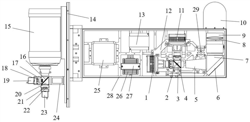
[0030] like figure 1 As mentioned above, there are multiple lasers, and each laser emits laser beams of different wavelengths; the emitting device also includes a beam splitter, and the laser beams emitted by each laser are combined into one beam and illuminate the mirror through the beam splitter; the discrete laser beam based on the imaging principle The atmospheric lidar system also includes a cage cube and a cage cube fixing seat 4 .

[0031] Specifically, the cage cube includes a first cage cube 2 and a second cage cube 20, the first cage cube 2 is fixed on the fixed rotating plate 12 of the transmitting device through the cage cube holder 4; the beam splitter includes the first beam splitter Sheet 3 and the second beam splitter 16; the first beam splitter 3 forms an angle of 45 degrees with the side of the first cage cube 2 and is vertically installed in the first cage cube 2 at the same time as the bottom surface of the first cage cube 2; the laser is a diode laser. T...

Embodiment 2

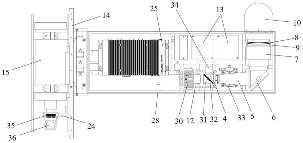
[0058] like figure 2 As mentioned above, the number of lasers is one; the emitting device also includes an observation camera 34 and a spectroscopic sheet 32, and the laser beam emitted by the laser is directed to the reflector through the spectroscopic sheet 32. The discrete atmospheric lidar system based on the imaging principle also includes a cage cube 31 and a cage cube fixing base 4 .

[0059] Specifically, the cage cube 31 is fixed on the fixed rotating plate 12 of the transmitting device through the cage cube fixing seat 4; In the cube 31; the laser is a diode laser 30; the diode laser 30 is arranged on one side of the cage cube 31 and is fixed on the fixed rotating plate 12 of the launching device; the observation camera 34 is arranged on the other side of the cage cube 31 and is fixed on the launcher The device is fixed on the rotating plate 12.

[0060]Further, the laser beam emitted by the diode laser 30 passes through the beam splitter 32 in the cage cube 31 an...


PUM


Abstract

The invention provides a discrete atmosphere laser radar system based on an imaging principle. The discrete atmosphere laser radar system comprises a host and a receiver. The receiver comprises a telescope and is detachably fixed on one side of the host; the host comprises a transmitting device, a transmitting device fixed rotating plate and a bottom plate, the transmitting device is fixed on the transmitting device fixed rotating plate, and the transmitting device fixed rotating plate is rotationally connected with the bottom plate; the transmitting device comprises a laser, a reflector and a lens; along with rotation of the transmitting device fixed rotating plate, the overlapping area of the laser emitted by the transmitting device and the view field of the telescope changes. By installing the reflector, the effect of folding the optical path of the laser is achieved, the system is compact in structure, meanwhile, the receiver is mounted on the host and is easy to disassemble, and the purposes that the system is smaller in size and more portable are achieved; after the lens is focused, the position of the lens is also fixed, the integrated design of the transmitting device is realized, and the effect of convenient adjustment is achieved.

Description

technical field [0001] The invention relates to the technical field of laser radar, in particular to a discrete atmospheric laser radar system based on imaging principles. Background technique [0002] Aerosol refers to the general term of liquid or solid particles suspended in the atmosphere. Although the content in the entire atmospheric environment is small, it has a vital impact on human health, public health and even the environment and climate. Therefore, the detection of the temporal and spatial distribution of the optical and microphysical properties of atmospheric aerosols is of great significance to the study of regional and global environmental and climate issues. Due to the limited size range of aerosol particles, the active remote sensing technology for atmospheric aerosol detection generally refers to lidar with lasers as radiation sources. At present, atmospheric aerosol lidar generally has problems such as large size, complicated adjustment, and difficulty i...

Claims


Application Information

Patent Timeline
IPC IPC(8): G01S7/481G01S7/483G01S17/95
CPCG01S7/481G01S7/483G01S17/95Y02A90/10
Inventor 梅亮孔政宫振峰
Owner DALIAN UNIV OF TECH
Why Eureka
Eureka Blog
Learn More