Electromagnetic heating device suitable for high-temperature and high-pressure working condition environment and using method of electromagnetic heating device

A heating device, high temperature and high pressure technology, applied in the direction of induction heating device, induction heating, induction heating control, etc., can solve the problems of high pressure environment leakage hidden danger, heater tube plate weld seams, narrow heating range, etc., to achieve replacement Excellent thermal effect, excellent high temperature performance, large heat transfer area

Active Publication Date: 2021-09-17
ZHENJIANG DONGFANG ELECTRIC HEATER
View PDF2 Cites 0 Cited by
  • Summary
  • Abstract
  • Description
  • Claims
  • Application Information

AI Technical Summary

Problems solved by technology

[0004] The purpose of the present invention is to provide an electromagnetic heating device suitable for high-temperature and high-pressure working conditions and its use method, so as to solve the problem of many heater tube plate welds, high-pressure environment leakage hazards, and high maintenance costs in the above-mentioned background technology. High, narrow heating range problem

Method used


Image

  • Electromagnetic heating device suitable for high-temperature and high-pressure working condition environment and using method of electromagnetic heating device
  • Electromagnetic heating device suitable for high-temperature and high-pressure working condition environment and using method of electromagnetic heating device
  • Electromagnetic heating device suitable for high-temperature and high-pressure working condition environment and using method of electromagnetic heating device

Examples


Embodiment Construction

[0036] The following will clearly and completely describe the technical solutions in the embodiments of the present invention with reference to the accompanying drawings in the embodiments of the present invention. Obviously, the described embodiments are only some, not all, embodiments of the present invention. Based on the embodiments of the present invention, all other embodiments obtained by persons of ordinary skill in the art without making creative efforts belong to the protection scope of the present invention.

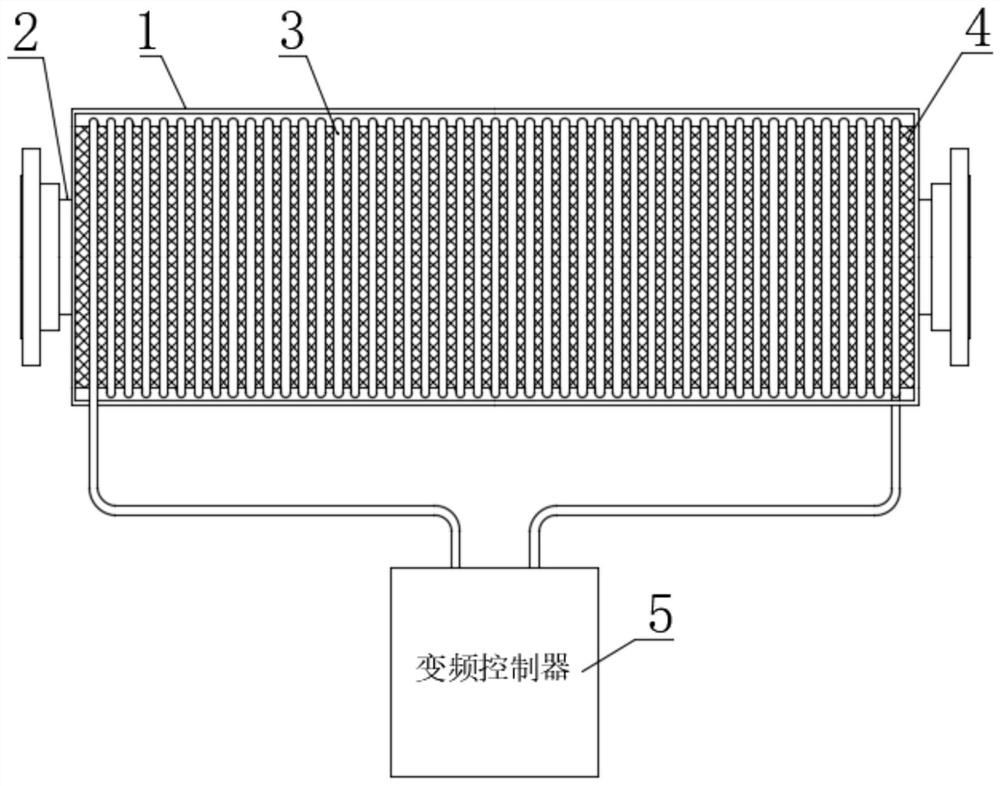
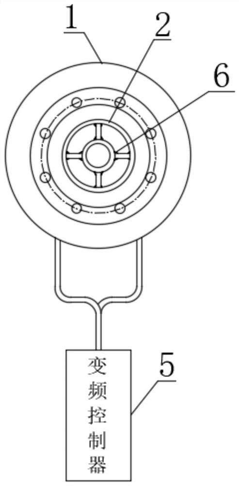
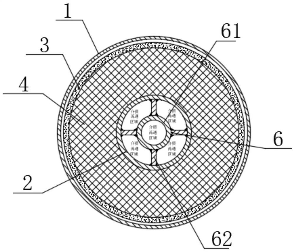
[0037] see Figure 1-3 , the present invention provides a technical solution: an electromagnetic heating device suitable for high-temperature and high-pressure working conditions and its use method, including a pressure vessel 2 arranged in the shield 1, and the pressure vessel 2 is located in the axial direction of the shield 1 At the center position, an electromagnetic induction coil 3 is arranged in the gap between the pressure vessel 2 and the shield 1, an...


PUM


Abstract

The invention discloses an electromagnetic heating device suitable for a high-temperature and high-pressure working condition environment and a using method thereof. The electromagnetic heating device comprises a pressure container arranged in a protective cover, the pressure container is located at the axial center position of the protective cover, and an electromagnetic induction coil is arranged in a gap between the pressure container and the protective cover; a magnetic conductive heating body for heat exchange is arranged in the pressure container, the magnetic conductive heating body comprises a heating column body and a plurality of heating plate bodies, the heating column body is mounted at the axial center position of the pressure container, and the plurality of heating plate bodies are annularly distributed around the heating column body; and the heating column body is fixedly connected with the inner wall of the pressure container through the heating plate bodies. According to the electromagnetic heating device suitable for the high-temperature and high-pressure working condition environment, the design that the pressure container and the magnetic conductive heating body are functionally separated is adopted, the electromagnetic heating device is safer, and the electromagnetic heating device is large in unit area heat load, large in heat exchange area, high in heating rate, wide in heating range of 0-1000 DEG C, few in tube plate weld joints, small in leakage hidden danger in the high-pressure environment and low in maintenance cost.

Description

technical field [0001] The invention belongs to the technical field of heaters, and in particular relates to an electromagnetic heating device suitable for high-temperature and high-pressure working conditions and an application method thereof. Background technique [0002] At present, the mainstream electric heaters on the market are divided into conventional resistance heaters, conventional electromagnetic heaters and infrared heating; conventional resistance heaters use electric current to emit heat through the electric heating body to heat the billet heating method, common resistance wire heating, ceramic Heaters, as well as resistance coil heating and quartz tube heating, are all resistive heating in principle. Conventional resistance heaters have small heat load per unit area, slow heating rate, no requirement for medium carrier, and generally the heating range is wide from 0 to 1000 ℃; while the conventional electromagnetic heater has a large heat load per unit area a...

Claims


Application Information

Patent Timeline
Patent Type & Authority Applications(China)
IPC IPC(8): H05B6/06H05B6/10
CPCH05B6/06H05B6/10
Inventor 赵延炜徐金华
Owner ZHENJIANG DONGFANG ELECTRIC HEATER
Why Eureka
Try Eureka