Brazing welding wire, brazing welding wire forming method and brazing welding wire forming die

A forming mold and brazing welding technology, which is applied to welding equipment, manufacturing tools, welding media, etc., can solve the problems of slow melting rate of flux, affecting welding quality, and long time, so as to improve welding quality and reduce heat transfer distance , The effect of convenient processing

Pending Publication Date: 2021-09-21
ZHENGZHOU RES INST OF MECHANICAL ENG CO LTD
View PDF13 Cites 1 Cited by
  • Summary
  • Abstract
  • Description
  • Claims
  • Application Information

AI Technical Summary

Problems solved by technology

[0005] However, during brazing, the heat used to melt the flux needs to be transferred from the outside to the inside through the hollow tube, the melting rate of the flux is slow, and it takes a long time for the flux to spread to the surface of the workpiece to remove the oxide film of the workpiece, which affects the welding quality

Method used


Image

  • Brazing welding wire, brazing welding wire forming method and brazing welding wire forming die
  • Brazing welding wire, brazing welding wire forming method and brazing welding wire forming die
  • Brazing welding wire, brazing welding wire forming method and brazing welding wire forming die

Examples


Embodiment 1

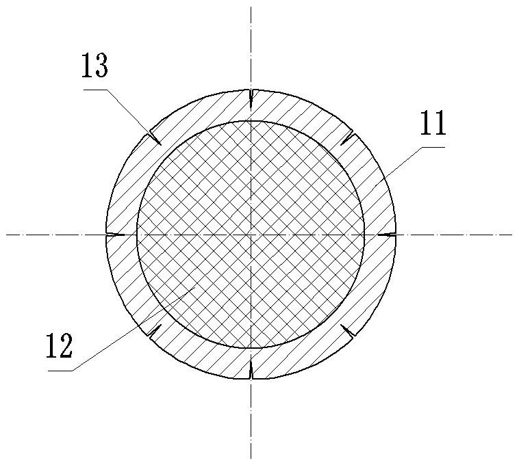
[0050] Such as figure 1 As shown, the brazing wire is used for welding glasses, and includes a brazing material tube 11 and a brazing flux 12 . The solder tube 11 is a seamless tube with an inner cavity, and the solder 12 is filled in the inner cavity of the solder tube 11 . The manufacturing method of the solder tube 11 and the filling method of the flux 12 are prior art, and will not be described in detail in the present invention. In order to prevent the flux 12 from absorbing moisture and affecting the activity of the flux 12, both ends of the solder tube 11 are closed.

[0051]The unique feature of the brazing wire in the present invention is that a groove 13 is provided on the outer peripheral surface of the solder tube 11 , and the cross section of the groove 13 is V-shaped, extending along the axis of the solder tube 11 . In this embodiment, the grooves 13 are evenly distributed along the circumferential direction, and the number is eight. The depth of the groove 13...

Embodiment 2

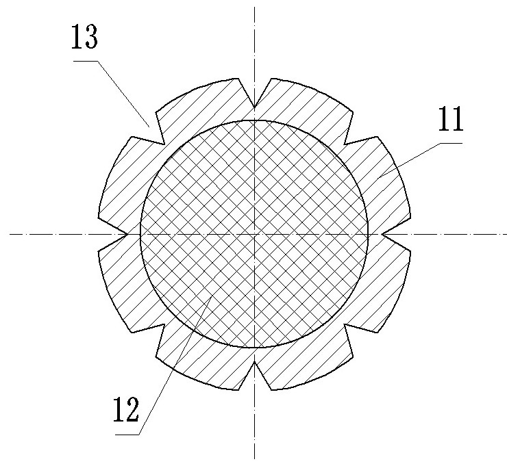
[0059] The difference from Example 1 is that this example figure 2 As shown, the width of the groove 13 on the outer peripheral surface of the solder tube 11 is relatively large, and the diameter reduction treatment in the above step 3 has not been performed.

[0060] Embodiment 1 of the brazing wire forming die among the present invention:

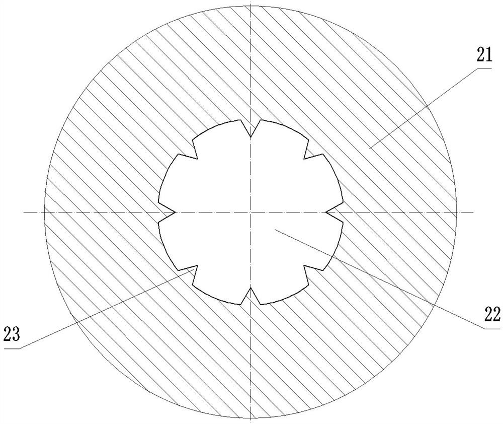
[0061] Brazing wire forming dies such as image 3 As shown, the inner wall of the forming cavity 22 is provided with a protrusion 23, and the protrusion 23 is used to form a groove 13 on the outer peripheral surface of the solder tube 11 when the brazing wire passes through the forming die.

[0062] Embodiment 2 of the brazing wire forming method among the present invention:

[0063] The difference from Embodiment 1 is that this embodiment only includes steps 1 and 2 of Embodiment 1, and does not include the diameter reduction process of Step 3.

Embodiment 3

[0065] The difference from Embodiment 1 or 2 is that in this embodiment, the brazing material tube 11 is firstly processed in steps 1 and 2, and finally the brazing flux 12 is poured.

[0066] In the above embodiment of the brazing wire, the cross section of the groove 13 is V-shaped, and in other embodiments of the brazing wire, the cross section of the groove 13 can also be other shapes, such as U shape, circular arc shape, trapezoid etc. Correspondingly, in other embodiments of the brazing wire forming die, the protrusion 23 on the inner wall of the forming cavity 22 may also be in other shapes, such as U-shape, arc-shape, trapezoid, and the like.

[0067] In other embodiments of the brazing wire, the number of grooves 13 can also be increased or decreased, for example, set to 3, 4, 5, 6, 7, 9 or 10, etc., or only Set 1 or 2 lanes. Correspondingly, in other embodiments of the brazing wire forming die, the protrusions 23 on the inner wall of the forming cavity 22 can also ...


PUM


Abstract

The invention relates to a brazing welding wire, a brazing welding wire forming method and a brazing welding wire forming die. The brazing welding wire comprises a brazing filler metal pipe with an inner cavity; and brazing flux filling the inner cavity of the brazing filler metal pipe, wherein a groove is formed in the peripheral face of the brazing filler metal pipe and extends along the axis of the brazing filler metal pipe or spirally extends around the axis of the brazing filler metal pipe. The brazing welding wire forming die comprises a die body, wherein a forming cavity is formed in the die body; a protrusion is arranged on the inner wall of the forming cavity, and when a brazing welding wire passes through the forming die, the protrusion is used for forming the groove in the peripheral face of the brazing filler metal pipe. The brazing welding wire forming method comprises the following steps: enabling a brazing filler metal pipe to pass through a forming mold; and forming a groove in the peripheral face of the brazing filler metal pipe through a protrusion arranged on the inner wall of a forming cavity of the forming die, wherein the groove extends along the axis of the brazing filler metal pipe or spirally extends around the axis of the brazing filler metal pipe. According to the scheme, the brazing flux melting rate of the brazing welding wire can be increased, the brazing flow laying time is shortened, and the welding quality is improved.

Description

technical field [0001] The invention relates to a brazing wire, a brazing wire molding method and a brazing wire molding die. Background technique [0002] Brazing wire and flux are often used in the brazing process. After the flux is melted, it can be spread on the surface of the workpiece to remove the oxide film on the surface of the workpiece, thereby improving the quality of brazing. [0003] For example, in the glasses industry, a pair of metal frames usually consists of 20 to 30 parts, mainly including glasses legs, frames, bridges, hinges, locking blocks, nose pads and screws, etc. Brazing is a traditional method of frames. connection method. At present, the annual output value of my country's glasses industry is high, and the domestic and foreign markets have great demand, but most of the products are still mainly made of low-grade materials such as brass and zinc white copper. With the advancement of technology, it is an important research direction for material ...

Claims


Application Information

Patent Timeline
Patent Type & Authority Applications(China)
IPC IPC(8): B23K35/02B23K35/40
CPCB23K35/0227B23K35/40B23K35/02B21C3/04B21C37/042B21C1/02
Inventor 钟素娟龙伟民裴夤崟张雷李秀朋沈元勋李云月王路乙
Owner ZHENGZHOU RES INST OF MECHANICAL ENG CO LTD
Why Eureka
Try Eureka