
A portable processing machine tool for mechanical processing

A technology of mechanical processing and processing machine tools, which is applied in the direction of metal processing machinery parts, metal processing equipment, manufacturing tools, etc. It can solve the problems of unable to quickly adjust the falling distance, unable to clean the cutting knife, and accelerate damage to the cutting knife, so as to avoid broken The effect of chip residue, easy processing, and flatness assurance

Active Publication Date: 2022-06-07
程旭
View PDF7 Cites 0 Cited by
  • Summary
  • Abstract
  • Description
  • Claims
  • Application Information

AI Technical Summary

Problems solved by technology

[0004] The present invention provides a portable processing machine tool for mechanical processing, which can effectively solve the problem that the actual size of the cutting knife cannot be quickly and directly detected when cutting a metal block in the above background technology, resulting in a decrease in the cutting distance. The inability to adjust quickly leads to different errors during cutting, which affects the use of gears. At the same time, the cutting knife cannot be cleaned quickly, which leads to the problem of accelerated damage of the cutting knife during cutting.

Method used


Image

  • A portable processing machine tool for mechanical processing
  • A portable processing machine tool for mechanical processing
  • A portable processing machine tool for mechanical processing

Examples


Embodiment

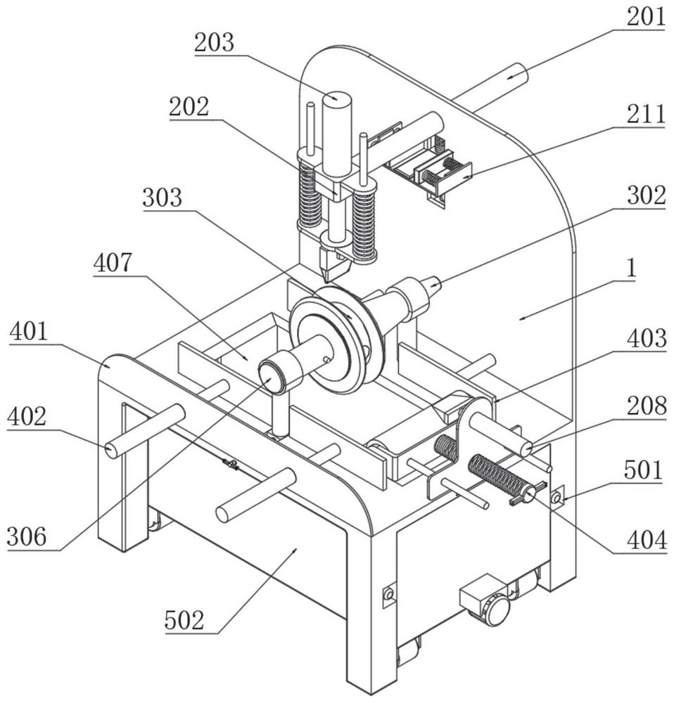
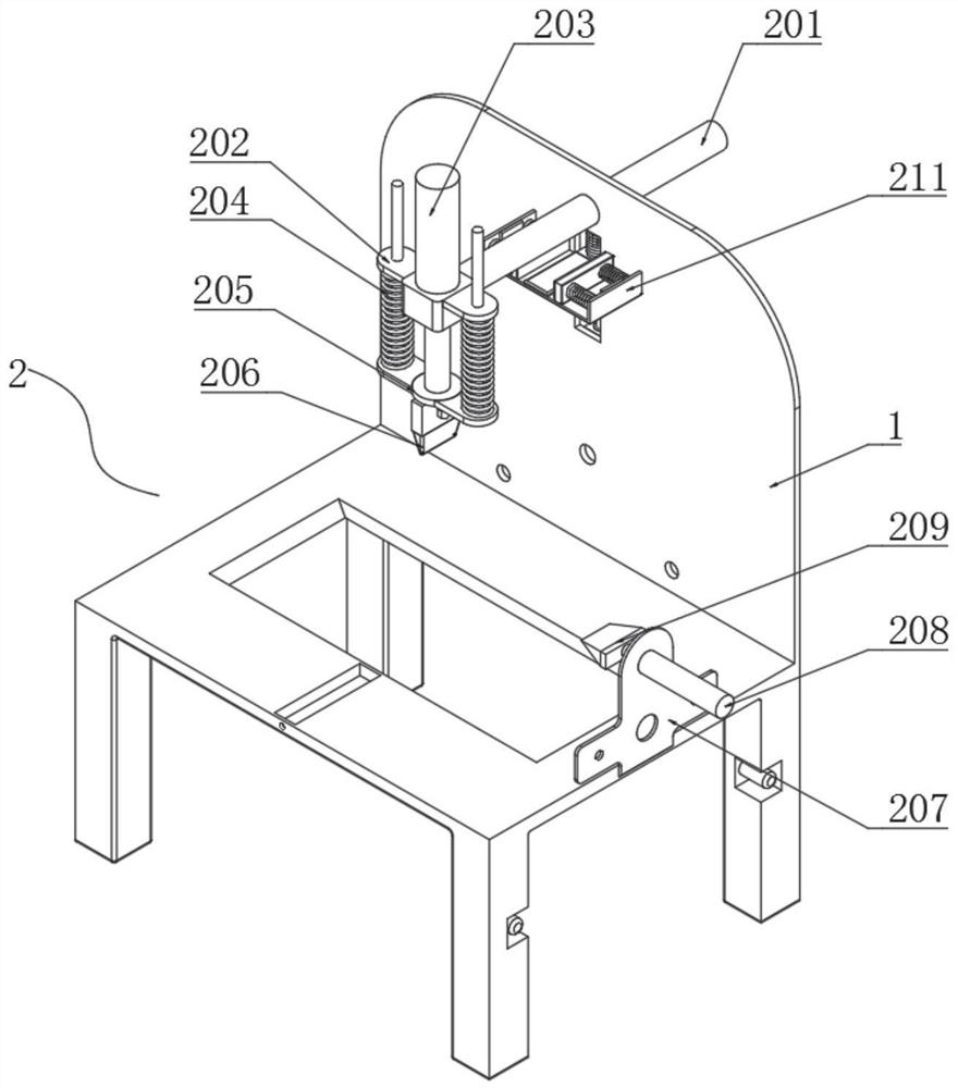
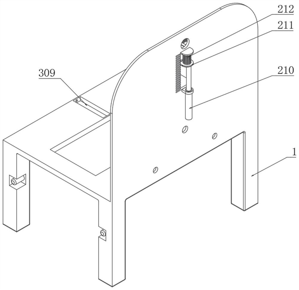
[0043] Example: as Figure 1-9 As shown, the present invention provides a technical solution, a convenient machining machine tool for machining, comprising a fixed support frame 1, a cutting assembly 2 is installed on one side of the fixed support frame 1, and the cutting assembly 2 includes a cutting hydraulic cylinder 201, a downward pressure Frame 202, lower piezoelectric push rod 203, lower pressure spring 204, fixed connection plate 205, cutting knife 206, fixed installation plate 207, push electric push rod 208, correction knife 209, ascending electric push rod 210, limit sliding plate 211 , stabilizing spring 212, protective spring 213, adsorption electromagnet 214, fixed protective box 215, cleaning cotton 216 and contact detector 217;

[0044] A cutting hydraulic cylinder 201 runs through one end of the fixed support frame 1 , and a lower pressure frame 202 is fixedly connected to one end of the cutting hydraulic cylinder 201 away from the fixed support frame 1 . The...


PUM


Abstract

The invention discloses a portable processing machine tool for mechanical processing. A cutting hydraulic cylinder runs through one end of a fixed support frame, a lower piezoelectric push rod runs through the middle of a lower pressure frame, and a cutting knife is embedded and connected to the inner side of a fixed connecting plate through a screw to push the electric motor. One end of the push rod is fixedly connected with a correction knife, cleaning cotton is placed inside the fixed protective box, and a contact detector is installed on the top of the limit sliding plate, and the lower pressing frame and the fixed connecting plate are driven by the cutting hydraulic cylinder and the lower piezoelectric push rod to move , so that the cutter can quickly and stably move to the side of the workpiece to cut the workpiece, and during the cutting process, the cutting hydraulic cylinder and the lower piezoelectric push rod drive the cutter to reset, and the rising electric push rod drives the limit sliding plate Ascending, so that the contact detector is directly attached to the bottom end of the cutting tool, so that the height of the pressing can be quickly adjusted during the cutting process, resulting in dimensional errors in cutting.

Description

technical field [0001] The invention relates to the technical field of machining, in particular to a convenient machining machine tool for machining. Background technique [0002] A machine tool refers to a machine that makes a machine, also known as a work machine or a tool machine, and is habitually referred to as a machine tool. There are many ways to process mechanical parts in modern machinery manufacturing: in addition to cutting, there are casting, forging, welding, stamping, extrusion, etc., but for parts with high precision and fine surface roughness requirements, generally need to be in The cutting method is used for final processing on the machine tool. At present, when making gears with larger sizes, direct cutting is required to ensure the strength of the gears. [0003] However, at present, when cutting metal blocks, it is impossible to quickly and directly detect the actual size of the cutting knife, resulting in the inability to quickly adjust the drop dista...

Claims


Application Information

Patent Timeline
Patent Type & Authority Patents(China)
IPC IPC(8): B23P23/02B23Q11/00B23Q11/10
CPCB23P23/02B23Q11/0042B23Q11/10
Inventor 程旭
Owner 程旭
Learn More