Novel material ceramic plate perforating machine

A technology of ceramic plate and punching machine, which is applied to stone processing tools, stone processing equipment, work accessories, etc., can solve the problems of brittleness of ceramic plates and the inability to clamp the curved ceramic plates, and achieve the effect of reducing flying everywhere.

Active Publication Date: 2021-09-21
西安隆昌建设有限公司
View PDF7 Cites 0 Cited by
  • Summary
  • Abstract
  • Description
  • Claims
  • Application Information

AI Technical Summary

Problems solved by technology

[0003] The embodiment of the present invention provides a new material ceramic plate punching machine, which solves the problem that the existing equipment cannot punch holes in arc-shaped ceramic plates. Very good clamping, and the ceramic plate is brittle, and the ceramic plate will have a small deformation under the action of external force, that is, the problem of fracture and damage

Method used


Image

  • Novel material ceramic plate perforating machine
  • Novel material ceramic plate perforating machine
  • Novel material ceramic plate perforating machine

Examples


Embodiment 1

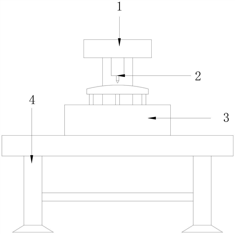
[0026] Such as figure 1 As shown, the present invention provides a new material ceramic plate punching machine, its structure includes a machine head structure 1, a drill bit 2, a fixing mechanism 3, a machine base 4, the surface of the machine base 4 is equipped with a fixing mechanism 3, and the machine The machine head structure 1 is fixed on the seat 4, and the machine head structure 1 is movably connected with the drill bit.

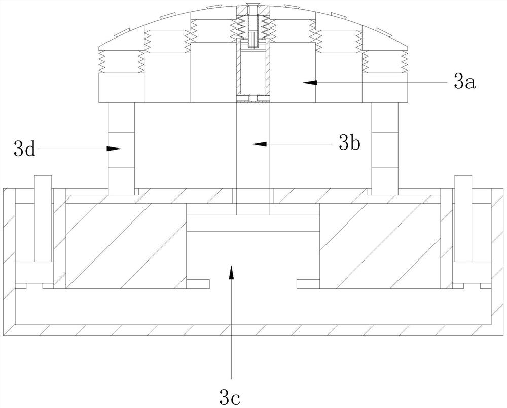
[0027] Such as Figure 2-3 As shown, the fixing mechanism 3 mentioned in the embodiment of the present invention includes a fixing tissue 3a, a pressing rod 3b, a base 3c, and a telescopic sliding rod 3d. The bottom of the fixing tissue 3a is equipped with a pressing rod 3b and a telescopic sliding rod 3d. There are two telescopic sliding rods 3d located on both sides of the pressing rod 3b, the pressing rods 3b cooperate with the base 3c, the telescopic sliding rods 3d are slidingly connected with the base 3c, and the base 3c is installed on the ...

Embodiment 2

[0036] Such as Figure 1-3 As shown, the present invention provides a new material ceramic plate punching machine, its structure includes a machine head structure 1, a drill bit 2, a fixing mechanism 3, a machine base 4, the surface of the machine base 4 is equipped with a fixing mechanism 3, and the machine The machine head structure 1 is fixed on the seat 4, and the machine head structure 1 is movably connected with the drill bit. The fixed mechanism 3 includes a fixed organization 3a, a pressing bar 3b, a base 3c, and a telescopic slide bar 3d. The bottom of the fixed organization 3a is installed There are compression rods 3b and telescopic sliding rods 3d. There are two telescopic sliding rods 3d located on both sides of the compression rods 3b. The compression rods 3b cooperate with the base 3c, and the telescopic sliding rods 3d are slidably connected to the base 3c. The base 3c is installed on the surface of the machine base 4 .

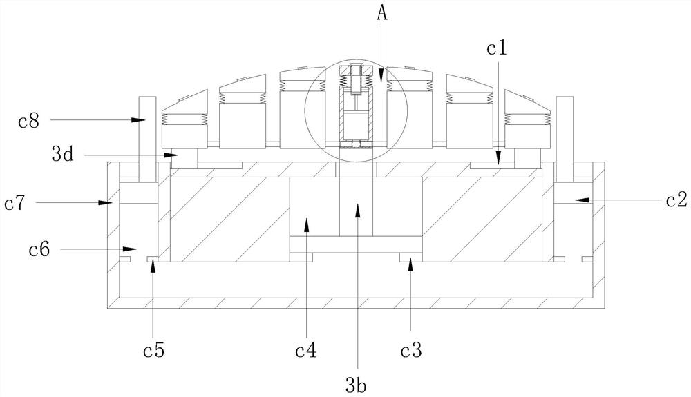
[0037] Such as Figure 4 As shown, th...


PUM


Abstract

The invention relates to the technical field of novel material processing, in particular to a novel material ceramic plate perforating machine which structurally comprises a machine head structure, a drill bit, a fixing mechanism and a machine base. The fixing mechanism is installed on the surface of the machine base, the machine head structure is fixed to the machine base, and the machine head structure is movably connected with the drill bit. The machine has the effects that original fixing through clamping force is changed into fixing through suction force, the influence of external force on an arc-shaped ceramic plate is reduced, the situation that the ceramic plate is broken and damaged due to small deformation generated under the external force effect in the machining process is prevented, tissue is fixed through an elastic air bag and a push-pull rod, and thus the machine can adapt to the ceramic plates with different radians. Meanwhile, a dust collecting box can automatically collect dust falling during machining, and the situation that the dust flies everywhere and destroys the cleanliness of the working environment is reduced.

Description

technical field [0001] The embodiments of the present invention relate to the technical field of new material processing, and in particular to a punching machine for a new material ceramic plate. Background technique [0002] New materials refer to newly developed or developing structural materials with excellent performance and functional materials with special properties. Structural materials mainly use their mechanical properties such as strength, toughness, hardness, and elasticity, such as new ceramic materials, metallic glass, etc. , in which the new ceramic material has its unique advantages in performance. In terms of thermal and mechanical properties, it has high temperature resistance, heat insulation, high hardness, wear resistance, etc. In terms of electrical properties, it has insulation, piezoelectricity, semiconductor, magnetism, etc.; in terms of chemistry, it has catalysis, corrosion resistance, adsorption, etc. In terms of biology, it has certain biocompat...

Claims


Application Information

Patent Timeline
Patent Type & Authority Applications(China)
IPC IPC(8): B28D1/14B28D7/02
CPCB28D1/146B28D7/02
Inventor 王一帆
Owner 西安隆昌建设有限公司
Why Eureka
Try Eureka