Multi-angle uniform electroplating equipment

A uniform electroplating, multi-angle technology, applied in the electrolysis process, electrolysis components, cells, etc., can solve the problems that the electroplating effect is not as good as the outer surface, affect the electroplating effect of the parts, and the electroplating effect is different, so as to avoid the contact between the sludge and the surface of the parts, improve the Work efficiency and productivity, the effect of improving the plating effect

Active Publication Date: 2021-09-21
创隆实业(深圳)有限公司
View PDF16 Cites 0 Cited by
  • Summary
  • Abstract
  • Description
  • Claims
  • Application Information

AI Technical Summary

Problems solved by technology

[0004] (1) In the existing electroplating equipment, when the part is being electroplated, the position and orientation of the part inside the equipment are unchanged, so there are certain differences in the electroplating effect of each side of the part, which is located on the innermost side of the part. The number of times it contacts the particles in the liquid is the least, so the electroplating effect is far inferior to the outer surface, which leads to different electroplating effects on each surface of the part and poor quality of the finished product;
[0005] (2) When the parts are being electroplated, the electrolytic liquid will generate certain bubbles, and the rise of the bubbles will drive the sludge inside the equipment to move upward together, so that the impurity particles will come into contact with the parts, which will seriously affect the electroplating effect of the parts

Method used


Image

  • Multi-angle uniform electroplating equipment
  • Multi-angle uniform electroplating equipment
  • Multi-angle uniform electroplating equipment

Examples


Embodiment Construction

[0035] The following will clearly and completely describe the technical solutions in the embodiments of the present invention with reference to the accompanying drawings in the embodiments of the present invention. Obviously, the described embodiments are only some, not all, embodiments of the present invention. Based on the embodiments of the present invention, all other embodiments obtained by persons of ordinary skill in the art without making creative efforts belong to the protection scope of the present invention.

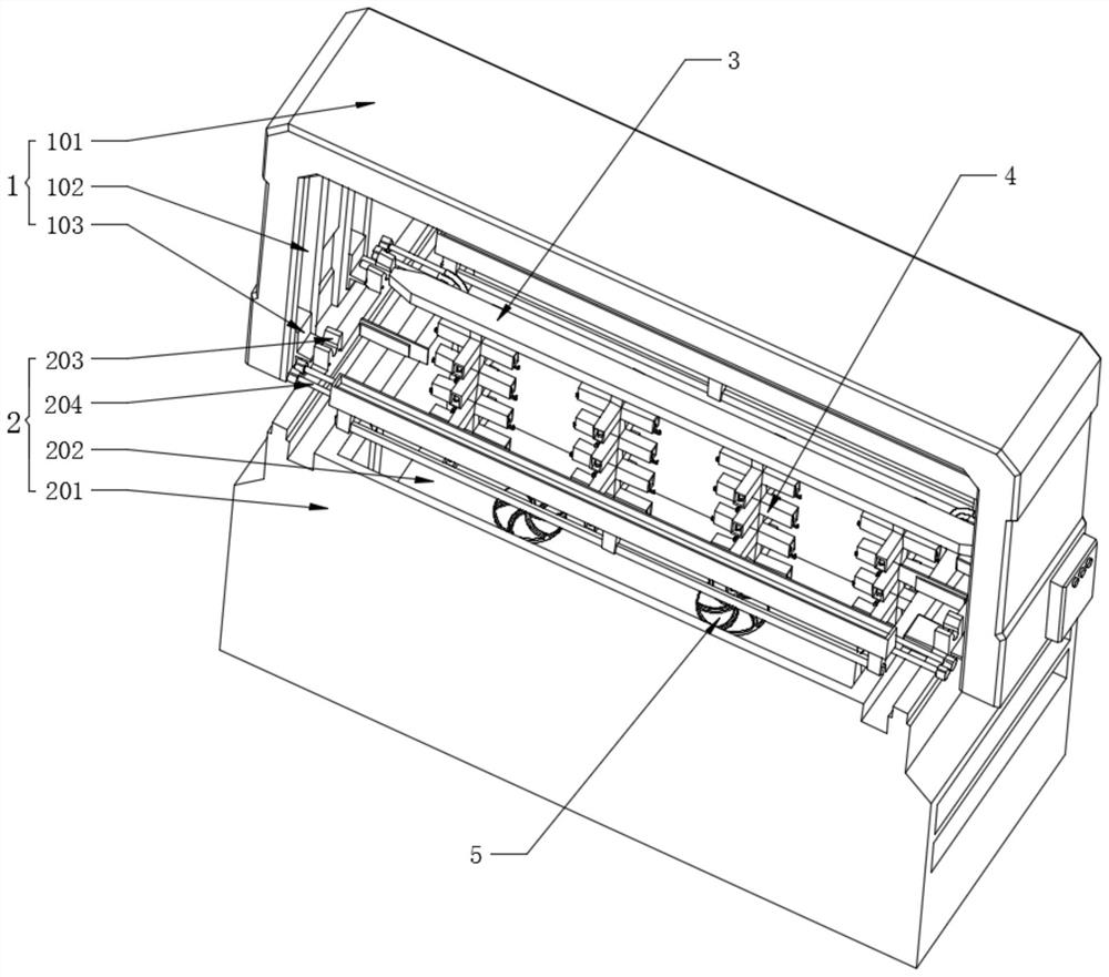
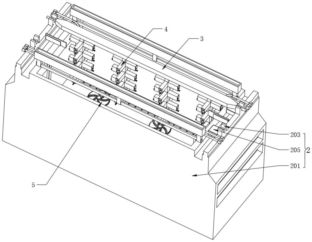
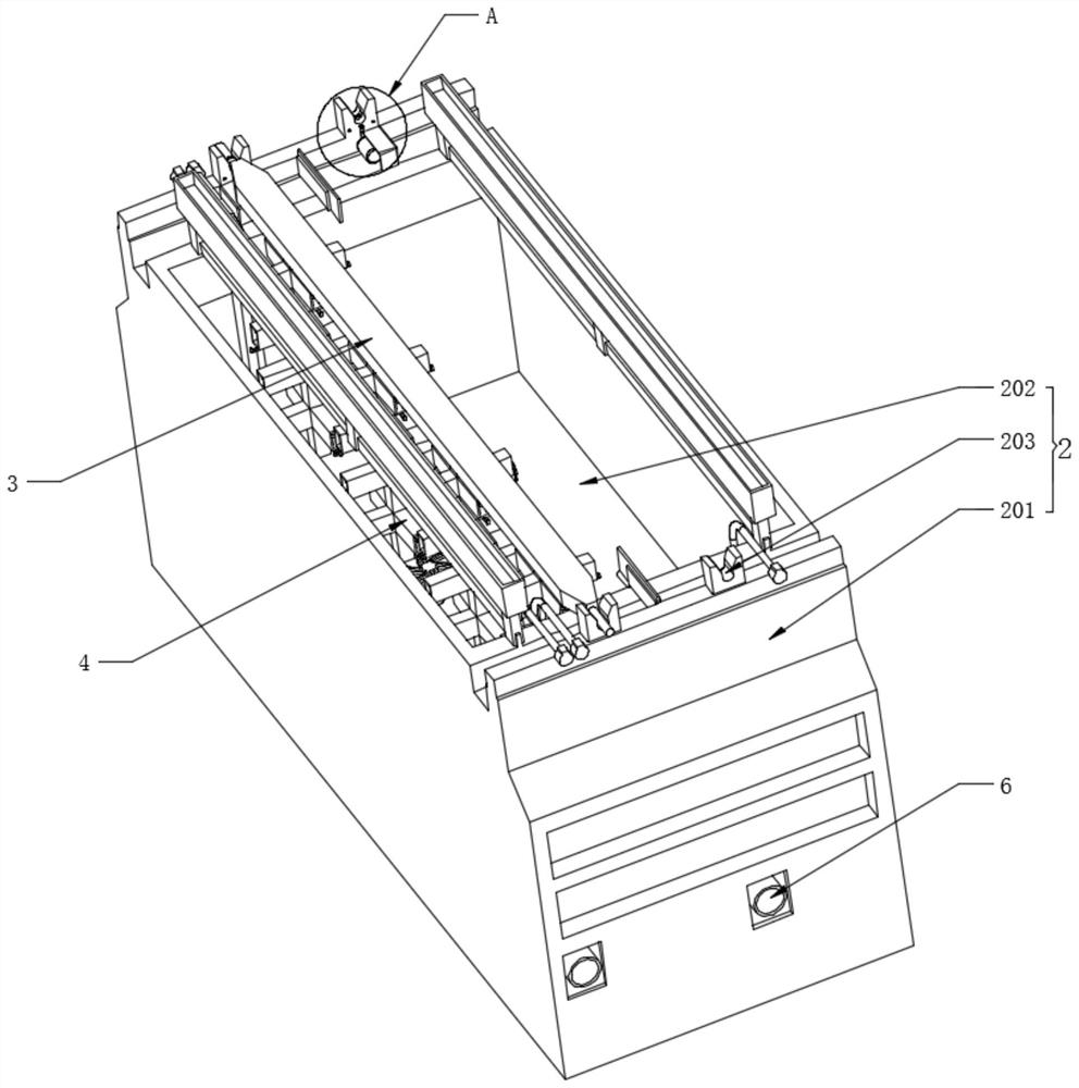
[0036] Please also refer to Figure 1-8 , figure 1 It is a schematic diagram of a three-dimensional structure in an embodiment of the present invention, figure 2 for figure 1 The schematic diagram of the three-dimensional structure of the electroplating device shown in the embodiment, image 3 for figure 1 The schematic diagram of the side view three-dimensional structure of the electroplating device shown in the embodiment, Figure 4 for image 3 The s...


PUM


Abstract

The invention discloses multi-angle uniform electroplating equipment. The multi-angle uniform electroplating equipment comprises a material conveying structure, an electroplating device, a belt material transmission structure, material hanging structures, a water flow generation device and a silt suction device. An electroplating bath is further arranged in the electroplating device; the material conveying structure is movably assembled on the outer surface of the top end of the electroplating bath; the belt material transmission structure is movably clamped in the electroplating bath; the material hanging structures are fixedly assembled on the lower surface of the belt material transmission structure at equal intervals; the water flow generation device is fixedly installed at the bottom end of the interior of the electroplating bath; and the silt suction device is fixedly arranged on the lower surface of the electroplating bath. The direction of a part is changed, all the surfaces of the part can make full contact with liquid, all the surfaces are electroplated evenly, the working efficiency, the electroplating speed and the yield are further improved, the phenomenon that sludge floats upwards is effectively avoided, and the multi-angle uniform electroplating equipment further has the advantages of energy conservation and emission reduction.

Description

technical field [0001] The invention relates to the technical field of electroplating equipment, in particular to a multi-angle uniform electroplating equipment. Background technique [0002] Surface conditions and processing requirements during electroplating, select appropriate steps, and perform necessary finishing on the surface of the parts to make the parts have a smooth and smooth surface. This is an important link to obtain high-quality coatings. In the pre-plating treatment process , the main equipment used are grinding, polishing machine, brushing machine, sandblasting machine, roller polishing machine and various fixing tanks. Electroplating treatment is the main process in the whole production process. According to the requirements of parts, a certain One or several single metal or alloy electroplating processes are used to process parts such as electroplating or immersion plating to achieve the purpose of corrosion resistance, wear resistance and aesthetics. The...

Claims


Application Information

Patent Timeline
Patent Type & Authority Applications(China)
IPC IPC(8): C25D17/08C25D21/10C25D21/00
CPCC25D17/06C25D21/10C25D21/00
Inventor 彭长明陈雪影
Owner 创隆实业(深圳)有限公司
Why Eureka
Try Eureka