
Coating apparatus

A coating device and coating technology, which is applied to the surface coating liquid device, coating, metal material coating process, etc., can solve the problems of device stoppage, bearing wear, etc., and achieve the effect of short soaking period

Inactive Publication Date: 2004-01-14
方丹工程机械有限公司
View PDF2 Cites 0 Cited by
  • Summary
  • Abstract
  • Description
  • Claims
  • Application Information

AI Technical Summary

Problems solved by technology

Therefore, such an arrangement is also necessarily accompanied by the above-mentioned bearing wear phenomenon, so that the corresponding roller must be replaced, and the device will be stopped at the same time.

Method used


Image

  • Coating apparatus
  • Coating apparatus
  • Coating apparatus

Examples


Embodiment Construction

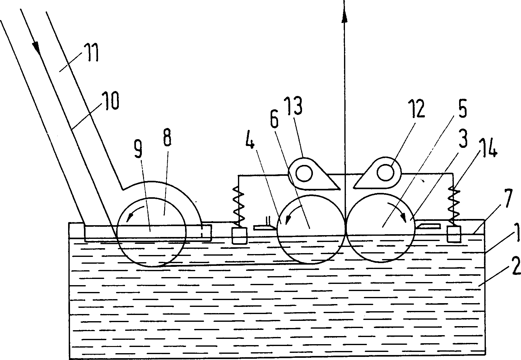
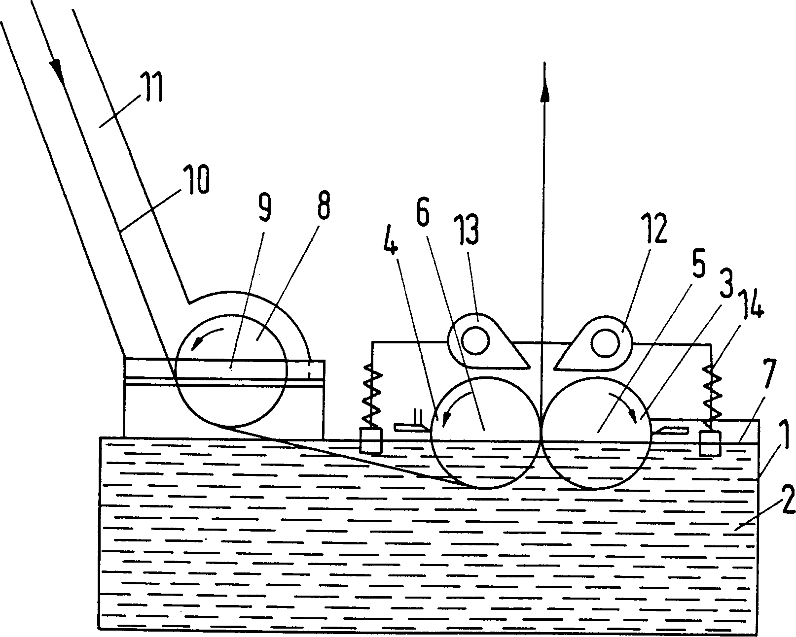
[0028] First of all figure 1 The coating device in is described according to its main structure, and a more detailed description is given in the description.

[0029] The coating device includes a paint container 1 and a coating tank 2 containing paint. The coating may include molten tin, zinc, aluminum, or multiple types of alloys, or water-soluble dyed powder. in figure 1 In the embodiment, the coating container 1 is a coating tank containing a coating tank 2.

[0030] The front coating drum 3 and the rear coating drum 4 are immersed in the coating bath, and their bearings 5 ​​and 6 are respectively located above the upper bath liquid level 7 of the coating bath 2.

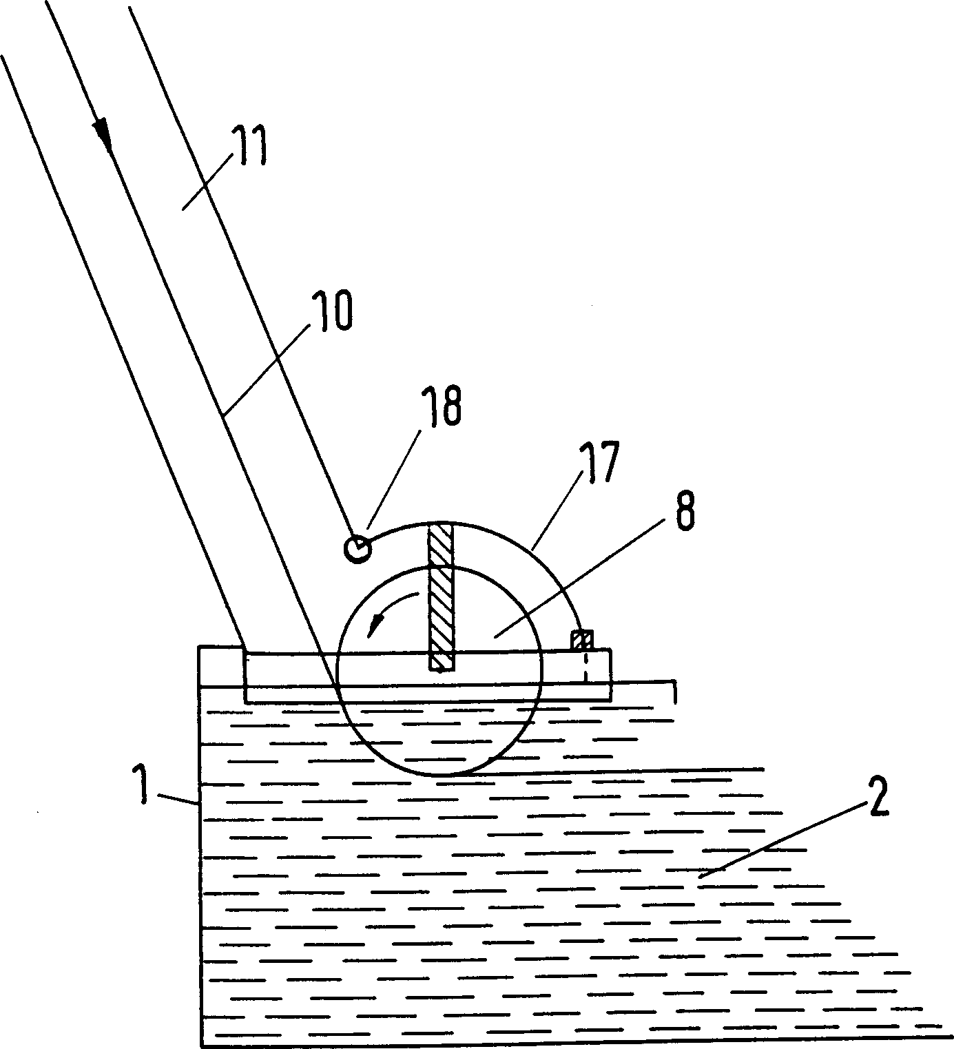
[0031] In this embodiment, the deflection roller 8 is also immersed in the coating bath 2. The bearing 9 of the drum is also located above the liquid level 7 of the upper bath of the coating bath 2.

[0032] The front and rear coating rollers 3 and 4 can be driven or not. The coating rollers 3 and 4 are separated ...


PUM


Abstract

A coating plant for coating strip-shaped material with covering material, in which the strip-shaped material which is to be coated is guided into a coating bath, and is guided between two coating rolls, which are partly immersed in the coating bath, out of the coating bath and past stripping nozzles, the bearings of the coating rolls being arranged outside of the coating bath. Preferably the strip-shaped material is guided into the coating bath by means of one or more deflector rolls of which at least one is arranged outside of the coating bath.

Description

Technical field [0001] The present invention relates to a coating device, which is used for coating strip-shaped material with paint, wherein the strip-shaped material to be coated is guided into a coating tank and is partially immersed in the coating tank from two coatings. Pass between the application rollers, leave the coating bath, and then pass through the stripping port. Background technique [0002] Various coating devices for coating strip-shaped materials have been known for a long time. The purpose of this type of device is to apply different liquid medium coatings, such as molten zinc, tin or its alloys, or dyeing materials, to coat different types of ribbon materials, such as metal ribbons, plastic ribbons, fabric ribbons or paper ribbons. The shape of the coating pool that applies tin or zinc to the strip-shaped material is like a molten pool in which the material is melted. [0003] The type of coating device mentioned at the beginning has been known for a long time...

Claims


Application Information

Patent Timeline
IPC IPC(8): C23C2/20B05C3/12B05C11/06C23C2/40
CPCB05C3/125B05C11/06B05C11/02
Inventor 帕斯卡尔·方丹
Owner 方丹工程机械有限公司
Learn More