
Screw compressor and oil separation barrel thereof

A technology of screw compressor and oil separation barrel, applied in the field of compressors, can solve the problems of treating symptoms but not the root cause, large noise, increasing the manufacturing cost and assembly complexity of screw compressors, etc., so as to improve flow efficiency, reduce noise, and improve oil and gas separation. The effect of efficiency

Inactive Publication Date: 2021-09-24
唐子怡
View PDF0 Cites 0 Cited by
  • Summary
  • Abstract
  • Description
  • Claims
  • Application Information

AI Technical Summary

Problems solved by technology

In order to separate compressed gas and lubricating oil, an oil separator barrel is usually installed on the compressor, but the traditional oil separator barrel can only play the role of oil and gas separation
At the same time, the screw compressor will generate a lot of noise when it is working, and its noise reduction measures are often supplemented by arranging noise reduction materials such as sound-absorbing cotton on the machine head. Although these components can effectively reduce part of the noise, they are all reduced from the noise source. Noisy, temporary solution but not the root cause, and increases the manufacturing cost and assembly complexity of the screw compressor

Method used


Image

  • Screw compressor and oil separation barrel thereof
  • Screw compressor and oil separation barrel thereof
  • Screw compressor and oil separation barrel thereof

Examples


Embodiment Construction

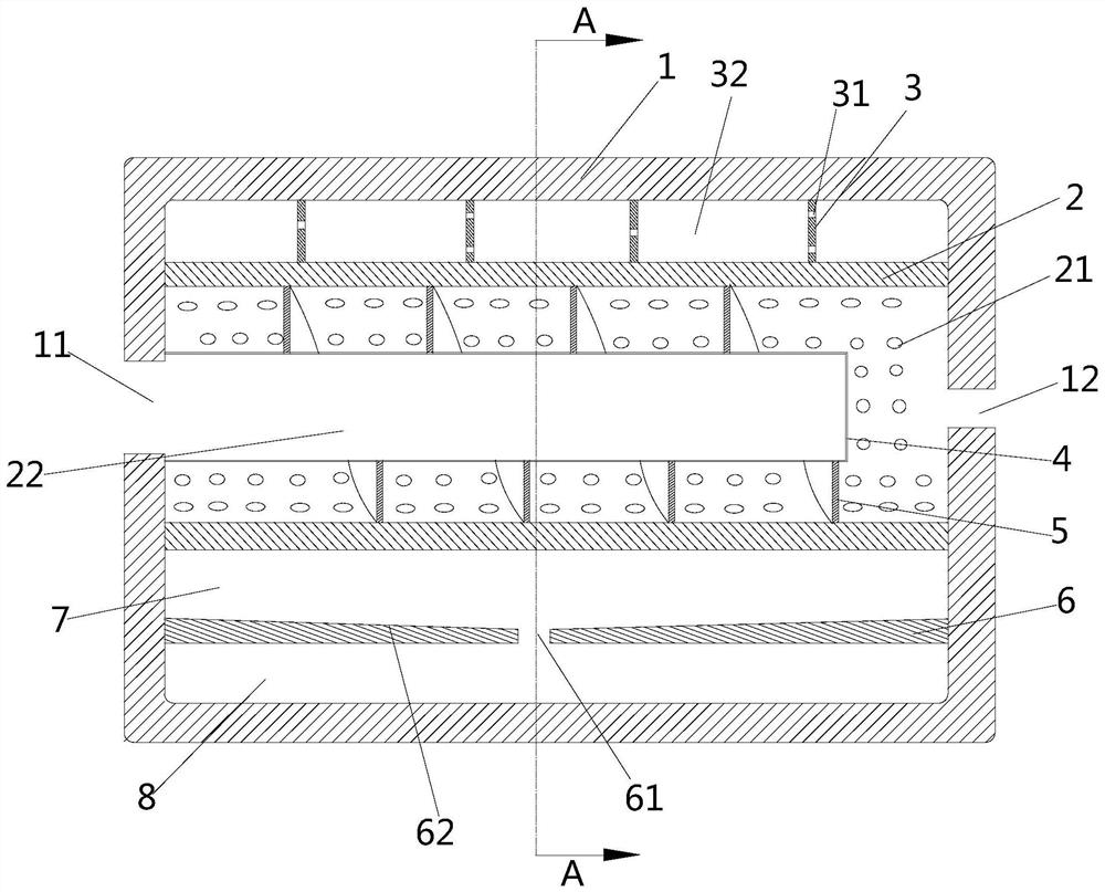
[0042] In order to explain the overall concept of the present application more clearly, the following detailed description will be given by way of examples in combination with the accompanying drawings.

[0043] In the following description, many specific details are set forth in order to fully understand the present invention. However, the present invention can also be implemented in other ways different from those described here. Therefore, the protection scope of the present invention is not limited by the specific details disclosed below. EXAMPLE LIMITATIONS.

[0044] In addition, in the description of the present invention, it should be understood that the terms "top", "bottom", "inner", "outer", "axial", "radial", "circumferential" and the like indicate an orientation or The positional relationship is based on the orientation or positional relationship shown in the drawings, which is only for the convenience of describing the present invention and simplifying the descrip...


PUM


Abstract

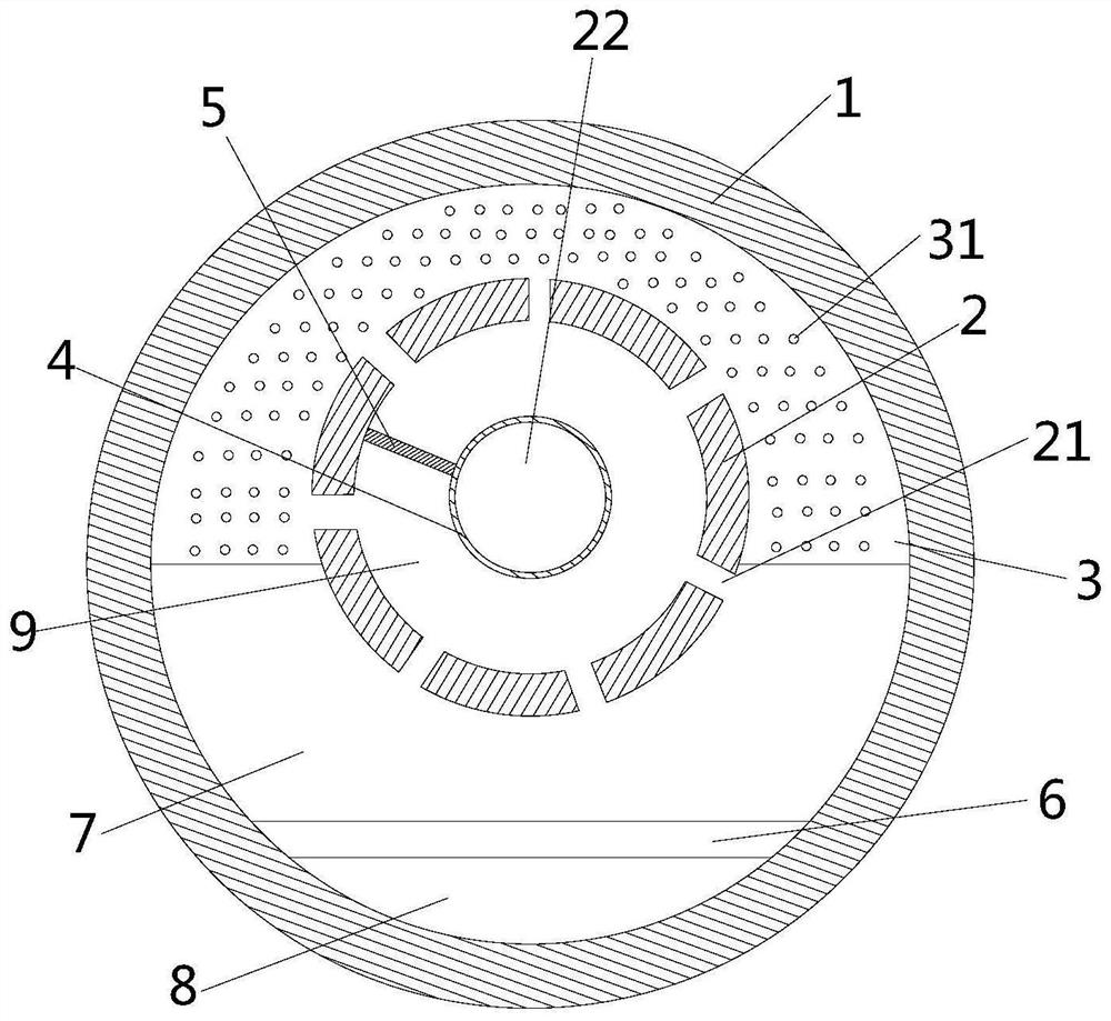
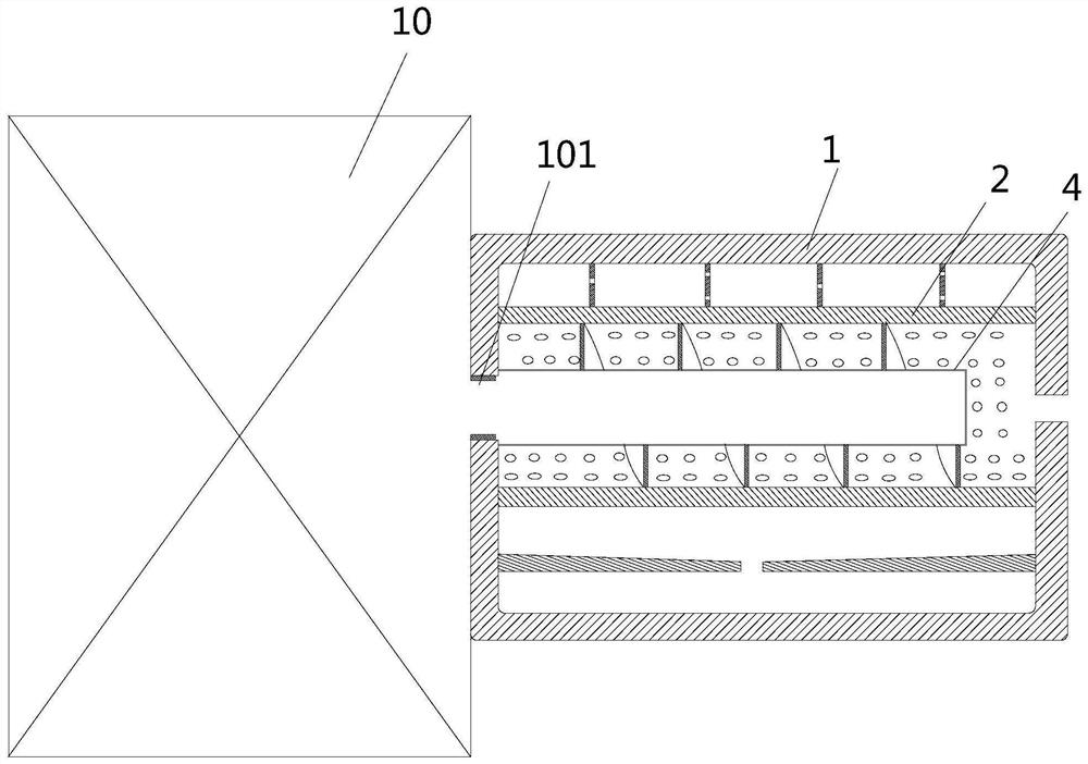
The invention discloses an oil separation barrel and an oil separation barrel thereof. The oil separation barrel comprises a shell with a containing cavity, the shell is provided with a port fixedly connected to an exhaust port of a screw compressor and an air outlet opposite to the port in position, wherein the oil separation barrel further comprises a column barrel arranged in the containing cavity and fixedly connected to the side wall of the oil separation barrel, a first opening communicating with the end opening is formed in one end of the column barrel, a second opening communicating with the air outlet is formed in the other end of the column barrel, the first opening and the second opening communicate to form an air exhaust channel, a plurality of first through holes communicating with the air exhaust channel are formed in the side wall of the column barrel, and the diameter of the air outlet is smaller than that of the exhaust port of the screw compressor. The invention further discloses the screw compressor applying the oil separation barrel. By using the oil separation barrel on the screw compressor, the noise generated by the screw compressor is greatly reduced, and meanwhile, the oil-gas separation efficiency is improved, so that the cost of the compressor is reduced.

Description

technical field [0001] The invention relates to the technical field of compressors, in particular to a screw compressor and an oil separator barrel thereof. Background technique [0002] Screw compressors have been more and more widely used in various industries to provide air power and air control instruments to provide compressed air. A certain amount of lubricating oil, these lubricating oils can play the role of lubrication, sealing and cooling, when the compression process is over, what is discharged from the compression chamber of the compressor host is a mixture of compressed gas and lubricating oil with a certain pressure and temperature , the oil-gas mixture. In order to separate compressed gas and lubricating oil, an oil separator is usually installed on the compressor, but the traditional oil separator can only play the role of oil and gas separation. At the same time, the screw compressor will generate a lot of noise when it is working, and its noise reduction ...

Claims


Application Information

Patent Timeline
Patent Type & Authority Applications(China)
IPC IPC(8): F04C29/02F04C29/06
CPCF04C29/026F04C29/06
Inventor 不公告发明人
Owner 唐子怡
Learn More