

Full-tunnel gas component monitoring method and system
A technology of gas composition and monitoring system, which is applied to the structural details of gas analyzers, analysis of gas mixtures, measurement devices, etc., can solve the problems of wasting manpower and material resources, a lot of manpower, and the size of tunnels is not small, and achieve the effect of saving manpower and material resources.
- Summary
- Abstract
- Description
- Claims
- Application Information
AI Technical Summary
Problems solved by technology
Method used
Image

Examples
Embodiment Construction
[0066] The following is attached Figure 1-3 The application is described in further detail.
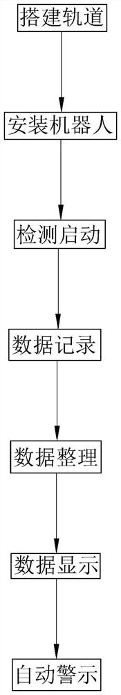
[0067] The embodiment of this application discloses a method for monitoring gas composition in a full tunnel, such as figure 1 As shown, the specific steps are as follows:
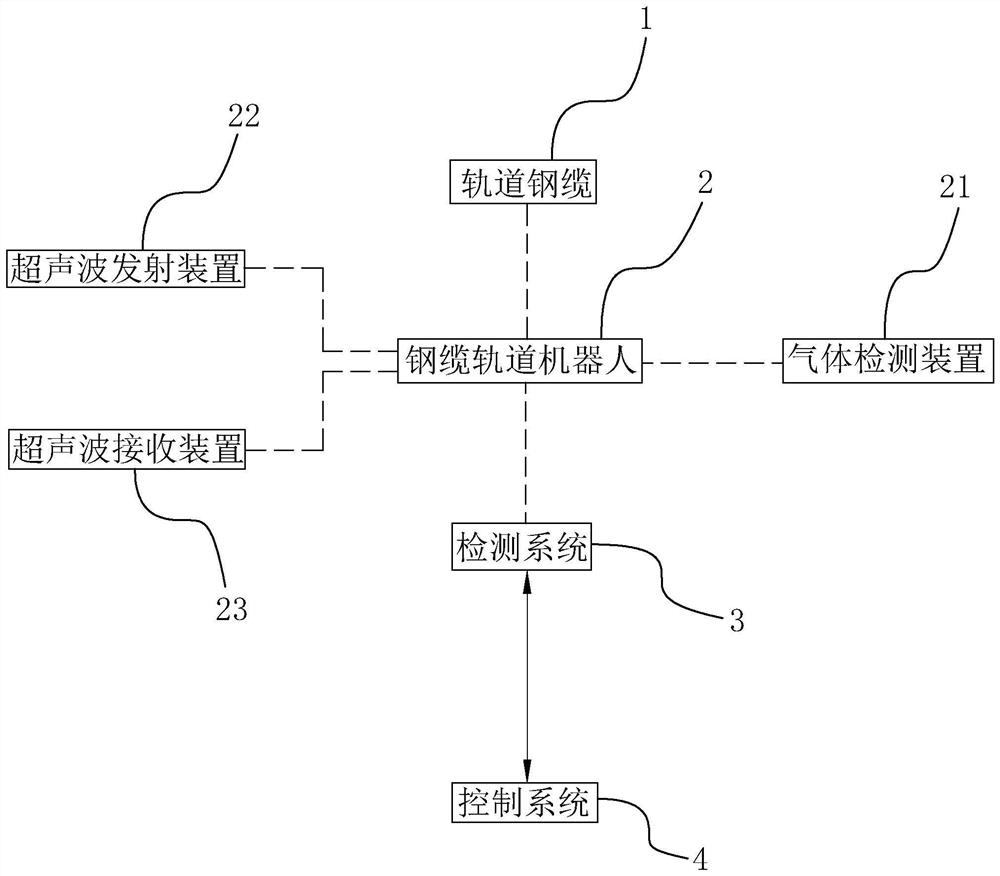
[0068] Such as figure 1 As shown, build the track: build the track steel cable 1 along the tunnel in the tunnel.
[0069] Such as figure 1 As shown, install the robot: select the gas detection device 21 according to the gas to be detected, and install the gas selection device on the cable track robot 2. There are multiple cable track robots 2, and all of them are installed on the track steel cable 1. Import cable track plans. Arrange the cable track robots 2 equidistantly on the cable track, obtain the track length between adjacent cable track robots 2, and record the standard track length.
[0070] Such as figure 1 As shown, start detection: After receiving the input start signal, control the steel cable ...
PUM
 Abstract
Description
Claims
Application Information