Probe driving structure of adjustable probe card device

A driving structure and probe card technology, which is applied in the field of probe cards, can solve problems such as poor contact, inconsistent height, deviation of probe height and pad or bump height, etc.

Pending Publication Date: 2021-09-24
范长旭
View PDF0 Cites 0 Cited by
  • Summary
  • Abstract
  • Description
  • Claims
  • Application Information

AI Technical Summary

Problems solved by technology

In order to ensure that the probes are in good contact with the pads or bumps on the chip, it is usually necessary to calibrate the probes, adjust the vertical and horizontal positions of the probes, and the height of the probes, but due to the solder pads or bumps on the chip The height of the block cannot be uniform, and there is still a deviation in the height direction between the probe and the pad or bump, resulting in poor contact

Method used


Image

  • Probe driving structure of adjustable probe card device
  • Probe driving structure of adjustable probe card device
  • Probe driving structure of adjustable probe card device

Examples


specific Embodiment approach 1

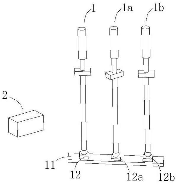
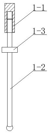
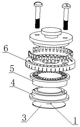
[0053] combine figure 1 As shown, an adjustable probe card device disclosed in this embodiment includes: a probe unit 1, a moving magnet 2, a probe card 3, a seat ring 4, a collar 5, a guide ring 6 and a probe wire 7, Several probe units 1 are arranged in an array, and a moving magnet 2 is arranged around the outer side of the probe unit array. The moving magnet 2 can move around the probe unit array, and a magnetic pole of the moving magnet 2 points to the probe unit during the movement. Array; the probe unit array is composed of probe unit 1, which is driven down by the micro-displacement of the probe station, and contacts with the bump 12 on the surface of the wafer 11 to realize the connection. After the high bump 12b contacts the probe unit 1b , at this time, the low bump 12a cannot be in contact with the probe unit 1a. By rotating the moving magnet 2 around a probe unit array, it moves around the probe unit array, and adjusts the probe unit 1a to move down, so that the p...

specific Embodiment approach 2

[0062] The following is an embodiment of a probe driving structure of an adjustable probe card device. The probe driving structure can be implemented alone, or can be used as a key structure of an adjustable probe card device disclosed in the first embodiment.

[0063] combine Figure 6 to Figure 8 As shown, a probe driving structure of an adjustable probe card device is used to drive the moving magnet 2 to rotate around the probe unit array, which can realize the clockwise and counterclockwise rotation of the moving magnet 2, and can use the moving magnet when needed 2. Move the moving magnet 2 to the vicinity of the probe unit array, and move the moving magnet 2 to a position away from the probe unit array when the moving magnet 2 is not needed to avoid the influence of the magnetic force.

[0064] The probe driving structure includes: a connecting frame 8-1, a damping disc 8-2, an external gear 8-3, an internal gear 8-4, a driving tooth 8-5 and a driving motor 8-6, and the ...

specific Embodiment approach 3

[0071] The following is an embodiment of a probe adjustment member of an adjustable probe card device. The probe driving device can be implemented alone, or can be used as a key structure of an adjustable probe card device disclosed in the first embodiment.

[0072] combine Figure 9 to Figure 11 As shown, a probe adjustment part of an adjustable probe card device is used to drive the moving magnet 2 to rotate around the probe unit array, which can realize the clockwise and counterclockwise rotation of the moving magnet 2, and can use the moving magnet when needed 2. Move the moving magnet 2 to the vicinity of the probe unit array, and move the moving magnet 2 to a position away from the probe unit array when the moving magnet 2 is not needed to avoid the influence of the magnetic force.

[0073] The probe driving device includes: connecting housing 9-1, driving device motor 9-2, driving wheel 9-3, transmission belt 9-4 and guide 9-5, one side of the connecting housing 9-1 is ...


PUM


Abstract

The invention belongs to the technical field of probe cards, and particularly relates to a probe driving structure of an adjustable probe card device, which comprises a connecting frame, a damping disc, an outer gear, an inner gear, driving teeth and a driving motor, the damping disc is rotatably arranged on the connecting frame, the outer gear is rotatably arranged on the lower side of the damping disc, the inner side of the outer gear is meshed with the inner gear, the outer side of the outer gear is meshed with the driving teeth, and the internal gear is provided with an arc-shaped limiting chute, so that when the driving teeth drive the outer gear to rotate, the internal gear firstly rotates to enable a movable magnet to be close to or far away from the probe unit array, the internal gear stops rotating after rotating to a limited angle, the outer gear drives the damping disc to rotate such that the movable magnet rotates around the probe unit array, the clockwise and anticlockwise rotation of the movable magnet can be realized, the movable magnet can be moved to a position near or far away from the probe unit array, and the influence of magnetic force is avoided.

Description

technical field [0001] The invention belongs to the technical field of probe cards, and in particular relates to a probe driving structure of an adjustable probe card device. Background technique [0002] In the wafer semiconductor production process, the quality of bare wafers needs to be tested after dicing and before packaging, to detect defective products, to screen out bad chips before packaging, to save packaging costs, and to know the quality of the wafer more directly. yield. During detection, the micro-displacement of the probe station drives the probe card to press down, and the probe card is used as a test interface for docking with the wafer. With the micro-displacement of the probe card, the probes on the probe card directly contact the pads or bumps on the chip to connect the circuit, lead out the chip signal, and achieve the purpose of measurement through the test instrument and software. In order to ensure that the probes are in good contact with the pads o...

Claims


Application Information

Patent Timeline
Patent Type & Authority Applications(China)
IPC IPC(8): G01R1/073G01R31/26
CPCG01R1/073G01R1/07307G01R1/07392G01R31/26
Inventor 范长旭
Owner 范长旭
Why Eureka
Try Eureka