Intelligent temperature control drinking water system
A drinking water system and intelligent temperature control technology, applied in beverage preparation devices, instruments, kitchen utensils, etc., can solve problems such as functional limitations, difficult water temperature, and difficulty in controlling the taste of tea
- Summary
- Abstract
- Description
- Claims
- Application Information
AI Technical Summary
Problems solved by technology
Method used
Image
Examples
Embodiment 1
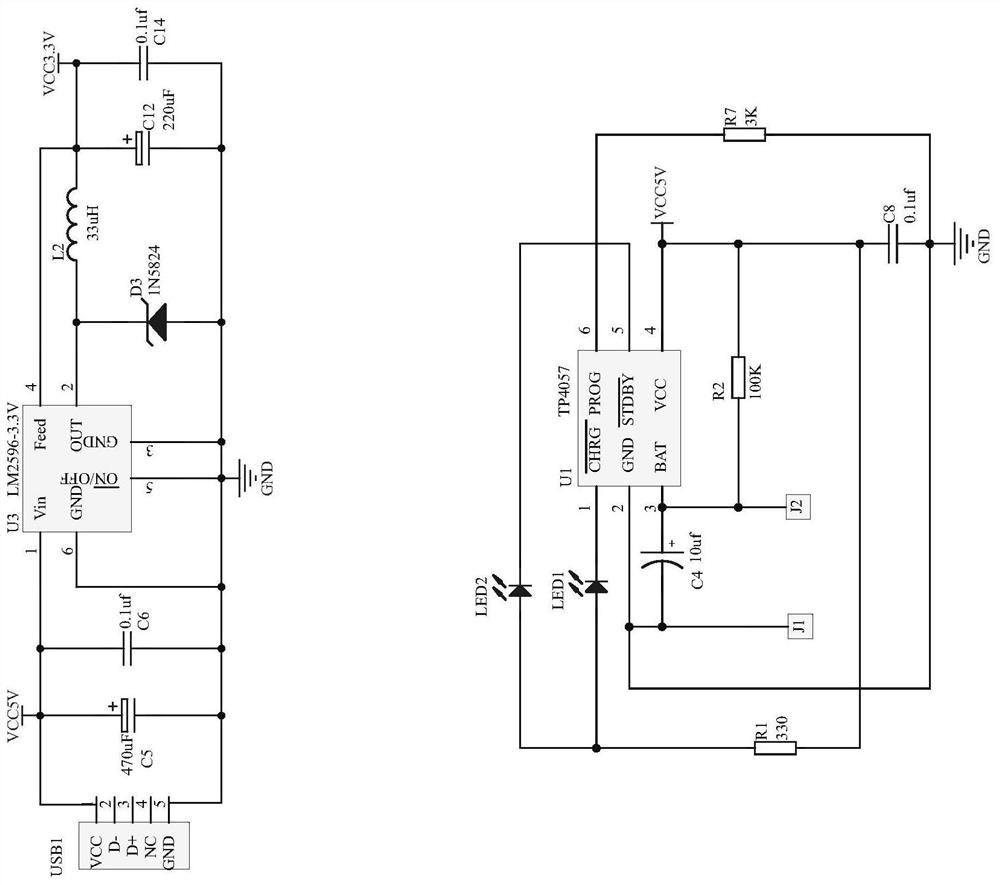
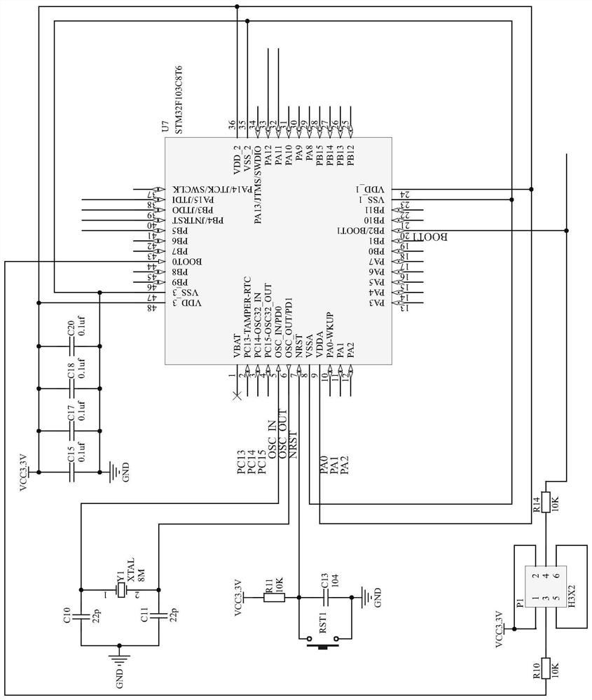
[0031] Example 1, such as Figure 1-8 As shown, an intelligent temperature-controlled drinking water system is provided, including: including: main control module, alarm module, cooling device circuit, weighing module, heating device circuit, Bluetooth, Ethernet control module, clock module, display module, power supply circuit, a temperature measurement module, and a button circuit, the main control module includes a chip U7, the temperature measurement module detects the temperature of the liquid in the system, the Ethernet control module and Bluetooth can realize remote control of the system by electronic equipment, The heating device and the cooling device regulate the temperature of the liquid in the system, and the weighing module can measure the mass of the solute that needs to be prepared.
Embodiment 2
[0032] Example 2, such as figure 1 As shown, the power supply circuit includes a battery charging circuit and a power supply voltage stabilizing circuit, the battery charging circuit includes a chip U1, the first lead of the chip U1 is connected to LED1, the resistor R1 is grounded, and the second lead is connected to the LED through LED2. The pin 5 of the chip U1, the first lead of the pin 2 of the chip U1 is connected to the pin 6 of the chip U1 through the resistor R7, the second lead is connected to the negative pole of the battery, and the pin 3 of the chip U1 is connected to the pole The positive pole of the polar capacitor C4, the positive and negative poles of the polar capacitor C4 are connected to the J1 and J2 poles of the battery, and the J1 and J2 poles of the battery are respectively connected to the power supply VCC and ground, and the capacitor C8 is set between the power supply VCC and the ground. Between the ground, the pin 4 of the chip U1 is connected to th...
Embodiment 3
[0034] Example 3, such as figure 2 As shown, the temperature measurement module includes chips U4, U5, U6A, and U6B. The first lead of the pin 1 of the chip U4 is connected to the pin 3 of the chip U6A through a diode D2 and a resistor R12, and the second lead is passed through The inductance L1 is connected to the power supply VCC, the first lead of the pin 2 of the chip U4 is connected to the power supply VCC through the resistor R3 and the capacitor C7, the second lead is connected to the pin 3 of the chip U6A through the resistors R9 and R12, and the chip U4 The pins 3 and 5 are connected to the power supply VCC, and the pin 6 is grounded. The model of the chip U4 is MT3608, the capacitor C9 is set between the 6V power supply and the ground, and the pin 1 of the chip U4 is connected to the tube of the chip U5. Pin 3, the first lead of the pin 3 of the chip U5 is grounded through a diode, the second lead is grounded through a resistor R13, the model of the chip U5 is TL431...
PUM
 Abstract
Description
Claims
Application Information
 - R&D
- Intellectual Property
- Life Sciences
- Materials
- Tech Scout
- Unparalleled Data Quality
- Higher Quality Content
- 60% Fewer Hallucinations
Browse by: Latest US Patents, China's latest patents, Technical Efficacy Thesaurus, Application Domain, Technology Topic, Popular Technical Reports.
© 2025 PatSnap. All rights reserved.Legal|Privacy policy|Modern Slavery Act Transparency Statement|Sitemap|About US| Contact US: help@patsnap.com


