
Light occlusion type under-wall strip-shaped foundation and construction method thereof

A strip-shaped basic and integrated technology, applied in basic structure engineering, construction and other directions, can solve the problems of financial consumption, material consumption, power consumption and environmental protection that cannot meet modern buildings, etc., and achieve the effect of improving labor productivity, saving construction period and light weight.

Pending Publication Date: 2021-10-01
LANZHOU UNIVERSITY OF TECHNOLOGY
View PDF0 Cites 2 Cited by
  • Summary
  • Abstract
  • Description
  • Claims
  • Application Information

AI Technical Summary

Problems solved by technology

[0003] At present, the traditional building foundation still adopts the cast-in-place method. Although the integrity of the cast-in-place foundation is superior, it gradually cannot meet the requirements of modern buildings in terms of financial consumption, material consumption, power consumption, and environmental protection.

Method used


Image

  • Light occlusion type under-wall strip-shaped foundation and construction method thereof
  • Light occlusion type under-wall strip-shaped foundation and construction method thereof
  • Light occlusion type under-wall strip-shaped foundation and construction method thereof

Examples


Embodiment 1

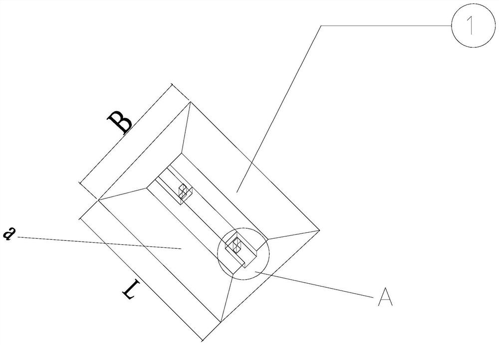
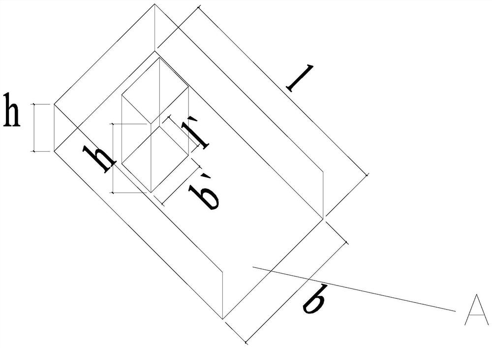
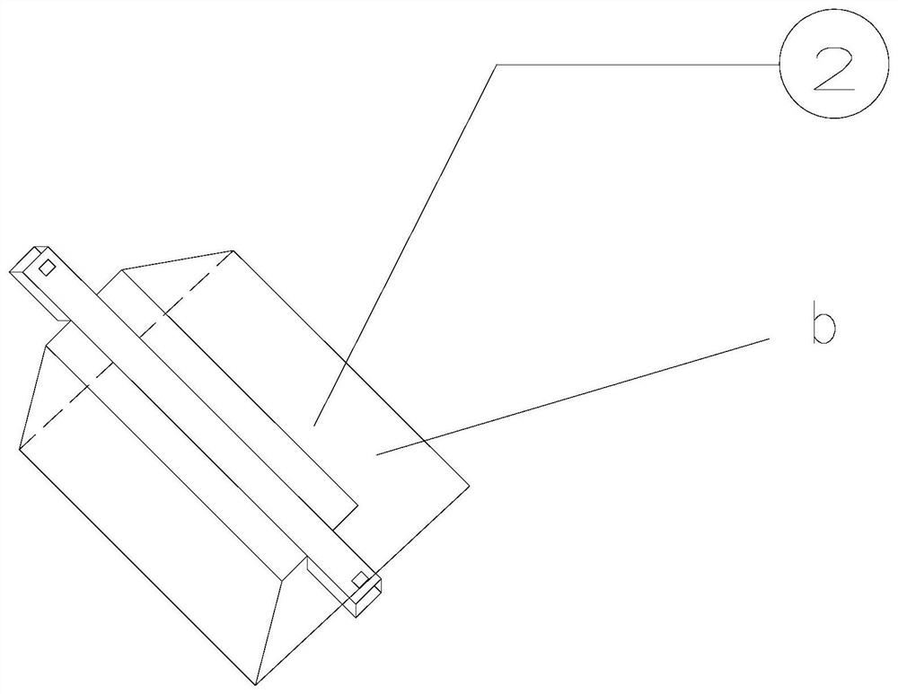
[0034] Embodiment 1, with reference to Image 6 As shown, in this embodiment, two mortise-type standard strip foundations 2 are interlocked and riveted to form a whole through mortise holes 7 and tenons 6 on one tenon-type standard strip foundation 1, wherein the tenon-type standard strip The longitudinal dimension L of the bottom surface of the shaped foundation 1 is smaller than the transverse dimension B, and a depression with a vertical length of l, a horizontal length of b, and a downward depth of h is left at the center of the two ends of the top surface of the foundation. A protruding tenon 6 with the tenon facing up, the bottom surface is connected to the bottom surface of the depression, the height of the tenon is h, the top surface is level with the top surface of other areas of the foundation, the transverse dimension of the tenon 6 is b', which is half of b, and the longitudinal length is l' It is half of l, and the tenon head 6 is located at the center of the bott...

Embodiment 2

[0035] Embodiment 2, with reference to Figure 7 As shown, the top surface of the bar-shaped foundation cross joint 3 in this embodiment is arranged with a tenon 6 at each of the four cross-shaped ends. The tenon holes 7 on the 2 are interlocked and riveted to form a whole.

Embodiment 3

[0036] Embodiment 3, with reference to Figure 8 As shown, the bar-shaped foundation right-angle joint 4 of this embodiment is provided with a tenon 6 on the two sides adjacent to the top surface, and the bar-shaped foundation right-angle joint 4 is connected with two mortise-type standard bar-shaped joints by two tenons 6. The tenon holes 7 of the foundation 2 are interlocked and riveted to form a whole.


PUM


Abstract

The invention discloses a light occlusion type under-wall strip-shaped foundation and a construction method thereof. The light occlusion type under-wall strip-shaped foundation comprises five standard components including a tenon type standard strip-shaped foundation, a mortise type standard strip-shaped foundation, a strip-shaped foundation cross joint, a strip-shaped foundation right-angle joint and a strip-shaped foundation T-shaped joint, wherein the tenon type standard strip-shaped foundation is in a tenon type in the longitudinal direction, the mortise type standard strip-shaped foundation is in a mortise type in the longitudinal direction, and the strip-shaped foundation cross joint, the strip-shaped foundation right-angle joint and the strip-shaped foundation T-shaped joint are in a tenon type in the longitudinal direction. All the standard components of the under-wall strip-shaped foundation are prefabricated in a factory, and the quality is reliable. The hoisting construction efficiency is high, and the construction period is shortened. All the standard components of the occlusion type under-wall strip-shaped foundation are connected in a mortise and tenon meshed mode, and the connection integrity between the standard components is high. The occlusion type under-wall strip-shaped foundation conforms to construction of small low-rise building foundations in rural areas, a series of construction steps such as formwork supporting, cast-in-place, heat preservation, moisture preservation and maintenance are avoided, and the cost is reduced.

Description

technical field [0001] The invention belongs to the technical field of building construction engineering, and specifically relates to a light-duty occlusal strip foundation under a wall and a construction method thereof. Background technique [0002] Traditional housing construction technology has low production efficiency, slow construction speed, long construction period, high material consumption and high labor intensity. These series of conditions can no longer meet the rigid demand for housing in modern society. The prefabricated building has the following characteristics: ①The design is diversified and can be designed according to the housing requirements; ②The function is modernized, and a variety of new materials such as energy saving and environmental protection can be used; ③Manufacturing is factory-based, which can make the building components and accessories uniform and factory-made. ; ④ Construction assembly can greatly reduce labor force and reduce material was...

Claims


Application Information

Patent Timeline
IPC IPC(8): E02D27/00
CPCE02D27/00
Inventor 朱彦鹏滕振银杜一博杨校辉吴林平赵壮福杜晓涛赵钰吕向向施多邦段新国
Owner LANZHOU UNIVERSITY OF TECHNOLOGY
Learn More