Energy-saving steam turbine unit waste steam waste heat recovery system
A technology of waste heat recovery system and steam turbine unit, which is applied in the field of exhaust steam recovery to achieve the effects of reducing flash steam volume, strong practicability, and improving economic benefits
- Summary
- Abstract
- Description
- Claims
- Application Information
AI Technical Summary
Problems solved by technology
Method used
Image


Examples
Embodiment 1
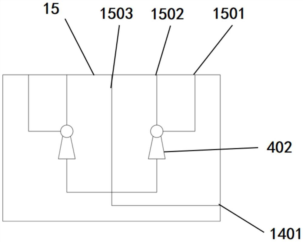
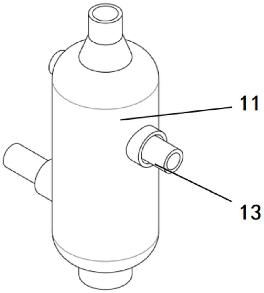
[0031] see Figure 1-Figure 8 , the present embodiment provides an energy-saving exhaust steam waste heat recovery system for a steam turbine unit, including a steam turbine unit 1, a exhaust steam separation system 2, a exhaust steam waste heat recovery system 3, an ejector 4, a water pump 5, a hot water supply port 6 and The hot water return port 7; the hot water supply port 6 communicates with the steam turbine unit 1; the exhaust steam separation system 2 includes a flash tank 8, a condensate tank 9, a water cooling box 10 and a pre-injection system 14; the ejector 4 includes a first The ejector 401 and the second ejector 402, the first ejector 401 and the water-cooled tank 10 are connected to the condensate tank 9, and the condensate tank 9 is connected to the hot water return port 7; the waste steam waste heat recovery system 3 includes a recovery tank 11, a pressurized Condenser 12, recovery tank 11 includes air inlet 1101, air outlet 1102, drain 1103, air valve 1104, s...
Embodiment 2
[0053] see figure 1 The second embodiment includes all the structures and beneficial effects of the first embodiment. The difference from the first embodiment is that the first injector 401 is also connected to the hydraulic switch 22 , and the hydraulic switch 22 is connected to the heater 23 .
[0054] When the water level of the condensed water in the flash tank 8 is too high, in order to ensure the normal operation of the flash tank 8 , the liquid level sensor 801 controls the hydraulic switch 22 to turn on, and the condensed water flows into the heater 23 . The heater 23 can heat the condensed water, and the heated condensed water flows into the booster valve 24 to increase the pressure. After the booster, the condensed water flows directly into the hot water supply port 6 through the pipeline to supply superheated steam for the steam turbine unit 1, thus increasing the flash rate. The flow rate of the drain port of the steam tank 8 keeps the liquid level of the condensed...
Embodiment 3
[0057] see Figure 4 Embodiment 3 includes all the structures and beneficial effects of Embodiment 1 and Embodiment 2. The difference between Embodiment 1 and Embodiment 2 is that the shower pipe 13 includes a shower head 1301, a nozzle body 1302 and a temperature sensor 1303. , the water pump 5 includes a third water pump 503 ; the nozzle body 1302 is connected to the hydraulic valve 25 and the water pump 503 , and the temperature sensor 1303 is installed on the nozzle body 1302 and electrically connected to the hydraulic valve 25 .
[0058] The temperature sensor 1303 can adjust the output flow of the third water pump 503 by controlling the hydraulic valve 25 according to the temperature of exhaust steam, so as to control the spraying amount of cooling water in the spray pipe 13, so that the waste heat of exhaust steam can be fully recovered without causing waste of cooling water .
[0059] The spray head 1301 is installed on the nozzle body 1302, and there are multiple spr...
PUM
 Abstract
Description
Claims
Application Information
 - R&D
- Intellectual Property
- Life Sciences
- Materials
- Tech Scout
- Unparalleled Data Quality
- Higher Quality Content
- 60% Fewer Hallucinations
Browse by: Latest US Patents, China's latest patents, Technical Efficacy Thesaurus, Application Domain, Technology Topic, Popular Technical Reports.
© 2025 PatSnap. All rights reserved.Legal|Privacy policy|Modern Slavery Act Transparency Statement|Sitemap|About US| Contact US: help@patsnap.com