Manufacturing method of high-current-impact-resistant lead-type aluminum electrolytic capacitor

An aluminum electrolytic capacitor and a manufacturing method of the technology are applied to electrolytic capacitors, solid electrolytic capacitors, wire wound capacitor machines, etc., and can solve problems such as capacity to be improved, current impact resistance, etc., and achieve simple and convenient structure realization, strong insulation, and structural fit effect

Inactive Publication Date: 2021-10-01
CHANGZHOU HUAWEI ELECTRONICS
View PDF5 Cites 0 Cited by
  • Summary
  • Abstract
  • Description
  • Claims
  • Application Information

AI Technical Summary

Problems solved by technology

[0005] The purpose of the present invention is to provide a method for making a lead type aluminum electrolytic capacitor with high current impact resistance, which solves the problem that the current impact resistance of the lead type aluminum electrolytic capacitor needs to be improved in the prior art

Method used


Image

  • Manufacturing method of high-current-impact-resistant lead-type aluminum electrolytic capacitor
  • Manufacturing method of high-current-impact-resistant lead-type aluminum electrolytic capacitor
  • Manufacturing method of high-current-impact-resistant lead-type aluminum electrolytic capacitor

Examples


Embodiment 1

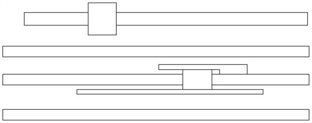
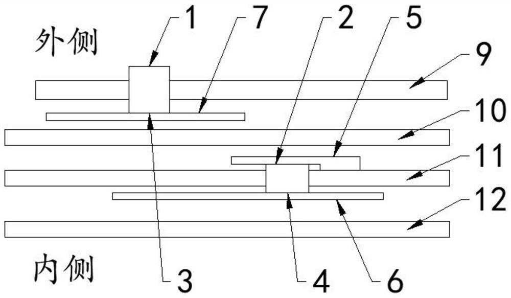
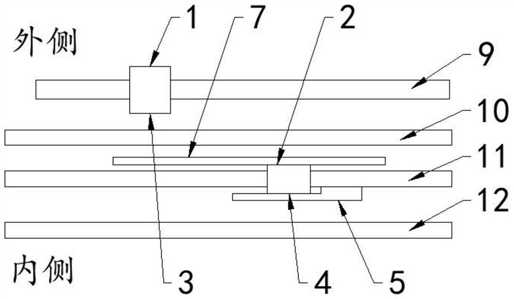
[0026] refer to Figure 1-4 , a method for making a high-current shock-resistant lead type aluminum electrolytic capacitor, comprising the following process: winding the negative electrode foil 11 outside the second electrolytic paper layer 12, winding the first electrolytic paper layer 10 outside the negative electrode foil 11, and An electrolytic paper layer 10 is wound around the positive electrode foil 9;

[0027] Wherein the negative electrode foil 11 and the positive electrode foil 9 are provided with electrode nails, the aluminum tongue end face 2 of the negative electrode nail faces the first electrolytic paper layer 10, the petal end face 4 of the negative electrode nail faces the second electrolytic paper layer 12, and the petal end face 3 of the positive electrode nail Towards the first electrolytic paper layer 10, an insulating layer is wound between the negative electrode nail aluminum tongue end face 2 and the positive electrode nail aluminum tongue end face 1, a...

Embodiment 2

[0030] refer to Figure 1-4 , a method for making a high-current shock-resistant lead type aluminum electrolytic capacitor, comprising the following process: winding the negative electrode foil 11 outside the second electrolytic paper layer 12, winding the first electrolytic paper layer 10 outside the negative electrode foil 11, and An electrolytic paper layer 10 is wound around the positive electrode foil 9;

[0031] Wherein the negative electrode foil 11 and the positive electrode foil 9 are provided with electrode nails, the aluminum tongue end face 2 of the negative electrode nail faces the first electrolytic paper layer 10, the petal end face 4 of the negative electrode nail faces the second electrolytic paper layer 12, and the petal end face 3 of the positive electrode nail Towards the first electrolytic paper layer 10, an insulating layer is wound between the negative electrode nail aluminum tongue end face 2 and the positive electrode nail aluminum tongue end face 1, a...

Embodiment 3

[0034] refer to Figure 1-4 , a method for making a high-current shock-resistant lead type aluminum electrolytic capacitor, comprising the following process: winding the negative electrode foil 11 outside the second electrolytic paper layer 12, winding the first electrolytic paper layer 10 outside the negative electrode foil 11, and An electrolytic paper layer 10 is wound around the positive electrode foil 9;

[0035] Wherein the negative electrode foil 11 and the positive electrode foil 9 are provided with electrode nails, the aluminum tongue end face 2 of the negative electrode nail faces the first electrolytic paper layer 10, the petal end face 4 of the negative electrode nail faces the second electrolytic paper layer 12, and the petal end face 3 of the positive electrode nail Towards the first electrolytic paper layer 10, an insulating layer is wound between the negative electrode nail aluminum tongue end face 2 and the positive electrode nail aluminum tongue end face 1, a...


PUM


Abstract

The invention relates to the technical field of lead-type capacitors, in particular to a manufacturing method of a high-current-impact-resistant lead-type aluminum electrolytic capacitor, and solves the problem that the current impact resistance of a lead-type aluminum electrolytic capacitor in the prior art needs to be improved. The manufacturing method of the high-current impact resistant lead type aluminum electrolytic capacitor comprises the following steps of: winding a negative electrode foil outside a second electrolytic paper layer, winding a first electrolytic paper layer outside the negative electrode foil, and winding a positive electrode foil outside the first electrolytic paper layer, wherein both the cathode foil and the anode foil are provided with electrode nails. According to the invention, the petal end face of the positive electrode nail and the petal end face of the negative electrode nail are respectively provided with the insulating layers, namely the second insulating layer and the first insulating layer, and the second insulating layer is additionally arranged on the petal end face of the positive electrode nail, so that the insulating strength between burrs on the petal end faces and the negative foil is improved, the impact endurance capability of instant large current or instant large voltage is improved, and thus the occurrence probability of point discharge is reduced.

Description

technical field [0001] The invention relates to the technical field of lead type capacitors, in particular to a method for manufacturing a lead type aluminum electrolytic capacitor resistant to large current impact. Background technique [0002] At present, the functions of the auxiliary gasket material of the nail coiling machine equipment for the production of lead-type aluminum electrolytic capacitors are as follows: figure 1 As shown, that is, the gasket negative foil gasket is placed on the outer aluminum tongue of the negative electrode foil lead-out electrode, the insulating paper gasket is placed on the inner side of the negative electrode foil lead-out electrode, and the positive electrode has no gasket. [0003] In the actual application of the whole machine, there are often instantaneous high currents or instantaneous high voltages that cause aluminum electrolytic capacitors to lead to electrode nails on the positive foil, and short-circuit breakdown failures occu...

Claims


Application Information

Patent Timeline
Patent Type & Authority Applications(China)
IPC IPC(8): H01G9/15H01G9/048H01G9/00H01G13/02
CPCH01G9/151H01G9/048H01G9/0003H01G13/02
Inventor 詹光耀何维满颜翰菁
Owner CHANGZHOU HUAWEI ELECTRONICS
Why Eureka
Try Eureka