
A vacuum interrupter

A vacuum interrupter and contact piece technology, applied in high-voltage air circuit breakers, high-voltage/high-current switches, electrical components, etc., can solve the problems of reduced breaking capacity, large contact diameter, and reduced conductive area, etc. The effect of improving breaking capacity, ensuring breaking capacity and reducing heat generation

Active Publication Date: 2022-04-15
SICHUAN UNIV
View PDF11 Cites 0 Cited by
  • Summary
  • Abstract
  • Description
  • Claims
  • Application Information

AI Technical Summary

Problems solved by technology

[0004] However, the current longitudinal magnetic contact system has the following defects: 1. When the cup-shaped longitudinal magnetic contact system is running at rated current, due to its complex structure and relatively reduced conductive area, the contact heat is serious, and in vacuum, there are two types of heat conduction and radiation. There are no other heat dissipation methods other than the heat dissipation method, so the room temperature of the entire vacuum interrupter will be too high, so that it cannot work under the condition of a large rated current; 2. Due to the complex structure of the contact, the diameter of the contact is often large, and the entire contact volume It is also large, so the operating mechanism needs more operating work when breaking (the cathode is a moving electrode, that is, a moving contact when breaking), which doubles the volume and cost of the operating mechanism, and it is not easy to meet the fast request for disconnection
[0005] Although the longitudinal magnetic field can better control the vacuum arc and increase the breaking current of the vacuum circuit breaker, the contact structure generating the longitudinal magnetic field is complex, which will reduce the rated operating current of the vacuum circuit breaker and increase the burden on the operating mechanism
Removing the complex longitudinal magnetic field structure can improve the above two situations, but it will significantly reduce the breaking capacity

Method used


Image

  • A vacuum interrupter

Examples


Embodiment Construction

[0032] The following will clearly and completely describe the technical solutions in the embodiments of the present invention with reference to the accompanying drawings in the embodiments of the present invention. Obviously, the described embodiments are only some, not all, embodiments of the present invention. Based on the embodiments of the present invention, all other embodiments obtained by persons of ordinary skill in the art without making creative efforts belong to the protection scope of the present invention.

[0033] The purpose of the present invention is to provide a vacuum interrupter to improve the breaking capacity of the vacuum circuit breaker while reducing the burden on the operating mechanism.

[0034] In order to make the above objects, features and advantages of the present invention more comprehensible, the present invention will be further described in detail below in conjunction with the accompanying drawings and specific embodiments.

[0035] Such as ...


PUM


Abstract

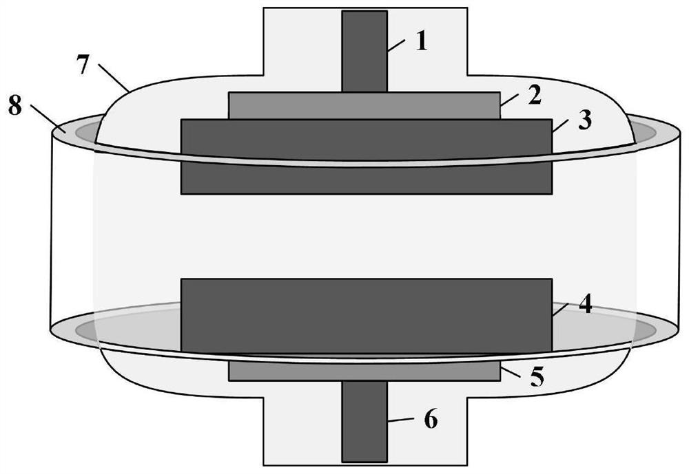
The present invention provides a vacuum interrupter, which comprises an anode side contact piece, a cathode side contact piece, an anode side conductive rod, a cathode side conductive rod and a cover arranged on the anode side contact piece, the cathode side contact piece, the anode side The side conducting rod, the shielding case on the periphery of the cathode side conducting rod and the outer magnet sleeved on the periphery of the shielding case. The present invention generates a fixed first longitudinal magnetic field in the interpolar region of the anode-side contact piece and the cathode-side contact piece by arranging an external magnet, which can ease the contraction of the arc when breaking the current, make the arc appear in a diffuse state, and reduce the arcing process The ablation of the contacts ensures the breaking capability of the vacuum circuit breaker. Compared with the cup-shaped longitudinal magnetic contact structure, the vacuum interrupter provided by the present invention is simple in structure, small in size and light in weight, which can effectively reduce the calorific value of the contact during operation at rated current, and reduce the burden on the operating mechanism. It is helpful to further improve the breaking capacity of the vacuum circuit breaker.

Description

technical field [0001] The invention relates to the field of electrical equipment, in particular to a vacuum interrupter. Background technique [0002] Circuit breakers play dual roles of protection and control in power systems, and their breaking performance is very important. Vacuum circuit breakers, which use vacuum as the insulation and arc-extinguishing medium, occupy an absolute dominant position in the medium-voltage field of power systems due to their excellent performance, and are currently developing in the direction of high voltage and high current. [0003] During the breaking process of the vacuum circuit breaker, the contact material evaporates and ionizes to form a vacuum arc plasma. The vacuum arc will produce an obvious shrinkage effect under the action of a strong magnetic pinch force in the magnetic field, which will cause severe ablation on the contact surface and flow to the arc. The column plasma provides a large amount of metal vapor and particles, ca...

Claims


Application Information

Patent Timeline
Patent Type & Authority Patents(China)
IPC IPC(8): H01H33/664H01H33/662H01H33/18
CPCH01H33/664H01H33/66261H01H33/182H01H33/66207H01H2033/66223
Inventor 黄小龙白雪艳陈维维朱海逸孙韬吴月峥洪果夏榆杭赵莉华任俊文宁文军
Owner SICHUAN UNIV
Learn More