Pre-charging device and three-level converter

A pre-charging, three-phase transformer technology, applied in circuit devices, battery circuit devices, current collectors, etc., can solve the problems of difficult device selection, high cost, and long return period.

Pending Publication Date: 2021-10-01
SHENZHEN HOPEWIND ELECTRIC CO LTD
View PDF5 Cites 0 Cited by
  • Summary
  • Abstract
  • Description
  • Claims
  • Application Information

AI Technical Summary

Problems solved by technology

However, the high-voltage protection devices, switching devices, and semiconductor devices introduced by device manufacturers have problems such as difficulty in device selection, high cost, and long return cycle.

Method used


Image

  • Pre-charging device and three-level converter
  • Pre-charging device and three-level converter
  • Pre-charging device and three-level converter

Examples


Embodiment 1

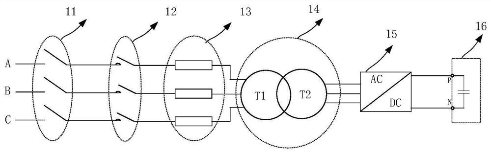
[0031] see image 3 and Figure 4 , image 3 It is a structural circuit diagram of the precharging device of the present invention; Figure 4 It is a structural circuit diagram of the first embodiment of the pre-charging device of the present invention; this embodiment discloses a pre-charging device, including a three-phase transformer 14, a first rectifier circuit 15, and a DC bus 16; the three-phase transformer 14 includes a first three-phase winding T1, the second three-phase winding T2; the first three-phase winding T1 is connected to a three-phase AC power supply through a three-phase AC cable; the three AC interfaces of the first rectifier circuit 15 are connected to the second three-phase winding of the three-phase transformer 14 T2 connection; the first rectifier circuit 15 is a three-phase diode uncontrolled rectifier circuit, the first rectifier circuit 15 includes three AC input interfaces and two DC output interfaces, and the three AC input interfaces are respec...

Embodiment 2

[0038] see Figure 5 , Figure 5 It is a structural circuit diagram of the second embodiment of the pre-charging device of the present invention;

[0039] In this embodiment, on the basis of Embodiment 1, the first rectifier circuit 15 includes a first single-phase uncontrolled rectifier bridge module 152, a second single-phase uncontrolled rectifier bridge module 153 and a third single-phase uncontrolled rectifier bridge module 154 , the first single-phase uncontrolled rectifier bridge module 152, the second single-phase uncontrolled rectifier bridge module 153 and the third single-phase uncontrolled rectifier bridge module 154 are three identical single-phase uncontrolled rectifier modules, and each single-phase uncontrolled rectifier module The rectifier bridge module includes an AC input interface C, a DC current outflow interface A+, and a DC current inflow interface B-, the DC current outflow interface A+ connected to the three single-phase uncontrolled rectification mo...

Embodiment 3

[0041] see Figure 6 , Figure 6 It is a structural circuit diagram of the third embodiment of the precharging device of the present invention;

[0042] In this embodiment, the first rectifier circuit includes a first diode series bridge arm 155, a second diode series bridge arm 156 and a third diode series bridge arm 157, the first diode series bridge arm The arm 155, the second diode series bridge arm 156 and the third diode series bridge arm 157 are three identical diode series bridge arms, and each of the diode series bridge arms is connected in series by n diodes in a manner consistent with the current direction. Each diode includes a current inflow connection point A and a current outflow connection point K, the connection point K of the first diode is used as the first connection point J1 of the diode series bridge arm, and the connection point of the nth diode A is used as the second connection point J2 of the diode series bridge arm, and the connection point A of th...


PUM


Abstract

The invention discloses a pre-charging device. The pre-charging device comprises a three-phase transformer, a first rectifying circuit and a direct-current bus, wherein the three-phase transformer comprises a first three-phase winding T1 and a second three-phase winding T2; the first rectifying circuit is a three-phase diode uncontrolled rectifying circuit and comprises three alternating-current input interfaces and two direct-current output interfaces, the three alternating-current input interfaces are respectively a first alternating-current input interface, a second alternating-current input interface and a third alternating-current input interface, and the two direct-current output interfaces are respectively a direct-current outflow interface and a direct-current inflow interface; and the first rectifying circuit is connected with a three-phase transformer and the direct-current bus. The invention further discloses a three-level converter. The pre-charging device performs transformation isolation through the transformer, the effect of pre-charging the direct-current bus of a middle-voltage converter and the direct-current bus of a high-voltage converter by using low-voltage common devices is achieved, cost is saved, and the reliability of a pre-charging loop is improved.

Description

technical field [0001] The invention relates to the field of circuit control, in particular to a precharging device and a three-level converter. Background technique [0002] With the development of wind power generation, converters are widely used. In order to avoid the current impact when the converter starts, causing the grid side circuit breaker to fail to close normally, or the semiconductor device to be damaged by overcurrent, it is necessary to pre-charge the bus capacitor to Realize the soft start of the converter. [0003] At present, the system voltage of converters widely used in the field of wind power generation is 690Vac. After years of development, protective devices, switching devices, and semiconductor devices suitable for 690Vac voltage levels have been serialized and mass-produced. In 690Vac system, it can be used as figure 1 The DC bus capacitor is pre-charged in the same way, the input power supply is the three-phase system voltage, and the output DC ...

Claims


Application Information

Patent Timeline
Patent Type & Authority Applications(China)
IPC IPC(8): H02J7/10H02M1/36H02M7/06
CPCH02J7/06H02M1/36H02M7/06H02J2207/20Y02E10/76
Inventor 周党生许亚明王武华王琰
Owner SHENZHEN HOPEWIND ELECTRIC CO LTD
Why Eureka
Try Eureka