
Vertical shaft shield tunneling machine and cutterhead system thereof

A technology of shield machine and cutter head, applied in shaft equipment, well sinking, mining equipment and other directions, can solve the problems of slow excavation, unfavorable use, low degree of mechanization, etc., and achieve the effect of maintaining stability and stabilizing the shaft wall

Pending Publication Date: 2021-10-08
山西工程技术学院
View PDF0 Cites 0 Cited by
  • Summary
  • Abstract
  • Description
  • Claims
  • Application Information

AI Technical Summary

Problems solved by technology

Whether it is the ordinary sinking method or the current mechanized excavation, workers need to go down the well and operate in a small space in the formation. This method has a slow excavation speed, low degree of mechanization, great safety risks for construction personnel, and high construction costs. Moreover, the slag removal method commonly used by shaft shield machines on the market today is mainly the downward slag removal method, but the downward slag removal method needs to excavate a slag transport channel at the bottom of the cave to transport the discharged slag, so that other The use conditions are very limited; it is not suitable for rock formation geology, which brings harsh requirements to the construction and is not conducive to use

Method used


Image

  • Vertical shaft shield tunneling machine and cutterhead system thereof
  • Vertical shaft shield tunneling machine and cutterhead system thereof
  • Vertical shaft shield tunneling machine and cutterhead system thereof

Examples


Embodiment

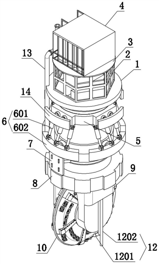
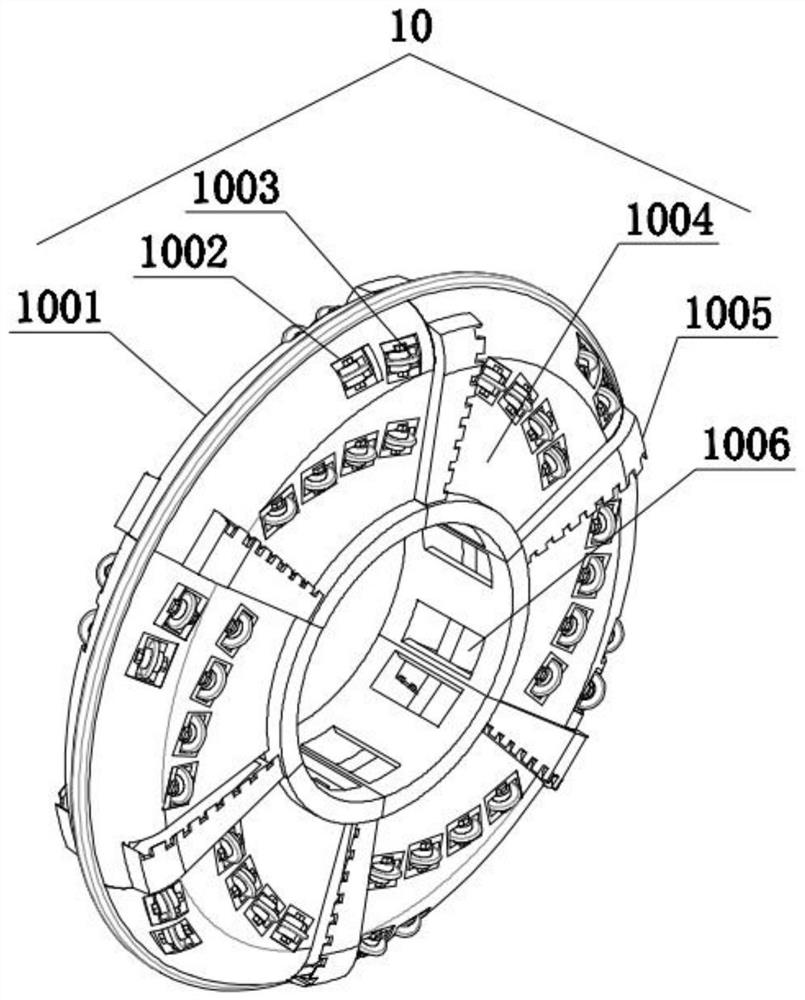
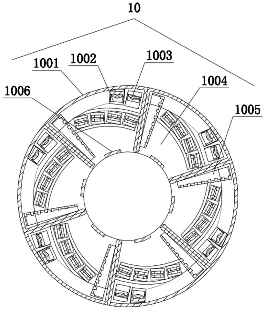
[0033] see Figure 1-4, a shaft shield machine and its cutter head system, including a working platform 1, an operating room 2 is fixedly installed on the top of the working platform 1, and a platform board 3 is fixedly connected to the top of the operating room 2, and the platform board 3 is fixedly installed with an equipment installation room 4, the bottom of the working platform 1 is fixedly connected with a main beam 5, and the outer upper end of the main beam 5 is fixedly installed with an expansion propulsion mechanism 6, and the outer side of the main beam 5 A segment assembly machine 7 is fixedly installed at the end, and a driving device 8 is fixedly installed at the outer lower end of the main beam 5. The bottom of the driving device 8 is fixedly connected with a mounting seat 9, and a tool is fixedly installed inside the mounting seat 9. A mechanism 10, a muck discharge mechanism 11 is fixedly installed in the inner center of the cutter mechanism 10, and a mud mech...


PUM


Abstract

The invention discloses a vertical shaft shield tunneling machine and a cutterhead system thereof, and belongs to the technical field of vertical shaft construction. The vertical shaft shield tunneling machine comprises a working platform, an operation room is fixedly mounted at the top of the working platform, a platform plate is fixedly connected to the top of the operation room, and an equipment mounting room is fixedly mounted at the top of the platform plate; a main beam is fixedly connected to the bottom of the working platform, an expanding and pushing mechanism is fixedly mounted at the upper end of the outer side of the main beam, a segment erector is fixedly mounted at the middle end of the outer side of the main beam, and a driving device is fixedly mounted at the lower end of the outer side of the main beam; and a mounting seat is fixedly connected to the bottom of the driving device, a cutter mechanism is fixedly mounted in the mounting seat, a muck discharging mechanism is fixedly mounted in the center of the interior of the cutter mechanism, and a slurry mechanism is fixedly mounted on the right side of the mounting seat. The expanding and pushing mechanism is arranged and used for supporting the well wall and adjusting the running direction of the equipment.

Description

technical field [0001] The invention relates to the technical field of shaft construction, and more specifically, relates to a shaft shield machine and a cutterhead system thereof. Background technique [0002] A shield machine is a tunnel boring machine that uses the shield method. The construction method of the shield tunneling machine is the "shield" of the tunnel built by the roadheader while digging, which is different from the open construction method. Internationally, the generalized shield machine can also be used in rock formations, but it is different from the open tunnel boring machine. In my country, tunnel boring machines used in soft ground are customarily called shield machines. According to the working principle, shield machines are generally divided into manual shield tunneling, extrusion shield tunneling, semi-mechanical tunnel tunneling, and mechanical tunnel tunneling. [0003] Coal mine shaft excavation technology up to now. Whether it is the ordinar...

Claims


Application Information

Patent Timeline
Patent Type & Authority Applications(China)
IPC IPC(8): E21D1/06E21F17/00
CPCE21D1/06E21F17/00
Inventor 张贵方董作峰李建伟刘旭李晓飞
Owner 山西工程技术学院
Learn More