Sludge low-temperature drying incinerator with waste heat recovery function
An incinerator and functional technology, applied in the field of incinerators, can solve the problem of not having waste heat recovery, and achieve the effect of avoiding waste of resources and realizing waste heat recovery.
- Summary
- Abstract
- Description
- Claims
- Application Information
AI Technical Summary
Problems solved by technology
Method used
Image

Examples
Embodiment 1
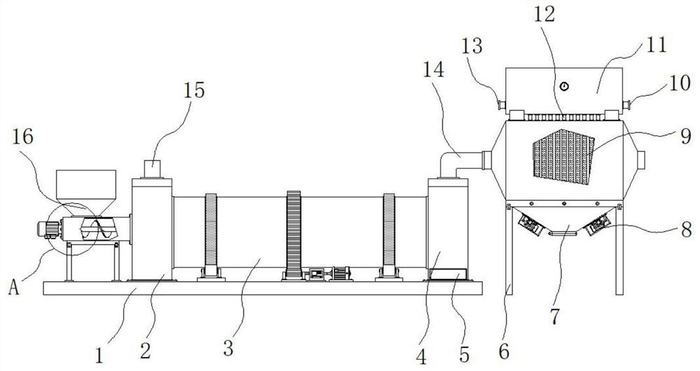
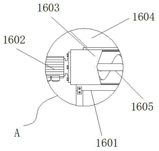
[0027] Example 1: See Figure 1-6 , a sludge low-temperature drying incinerator with the function of recovering waste heat, comprising a bottom plate 1, the top of the bottom plate 1 is fixedly connected with a front-end bin 2, one side of the top of the bottom plate 1 is fixedly connected with a rear-end bin 4, the front-end bin 2 and A rotary incineration kiln body 3 is arranged horizontally between the rear bins 4, a slag outlet 5 is arranged at the bottom end of the front end of the rear bin 4, a first frame body 6 is arranged on one side of the bottom plate 1, and the top of the first frame body 6 The heat chamber 7 is fixedly connected, the top of the front chamber 2 is provided with an air inlet 15, the side of the heat chamber 7 and the top of the rear chamber 4 are fixedly connected with a smoke guide pipe 14, and the top of the heat chamber 7 is provided with a waste heat recovery structure;
[0028] see Figure 1-6 , a sludge low-temperature drying incinerator wit...
Embodiment 2
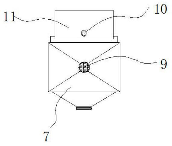
[0030] Embodiment 2: The conduit 12 runs through the top of the heat chamber 7 and communicates with the interior of the water storage tank 11, the finned tubes 9 are arranged at equal intervals, and the conduits 12 are symmetrically distributed about the vertical center line of the water storage tank 11 to make the heating more uniform ;
[0031] Specifically, such as figure 1 and figure 2 As shown, hot water can be drawn out along the outlet 10 for domestic or production water, and at the same time, new cooling water is continuously injected from the water inlet 13 to make full use of heat energy, avoid waste of resources, and realize the function of waste heat recovery.
Embodiment 3
[0032] Embodiment 3: The bottom ends of both sides of the hot chamber 7 are provided with a quick ash discharge mechanism 8, and the fast ash discharge mechanism 8 is composed of a fixed plate 801, a protective shell 802, an inspection cover 803, a servo motor 804, and an eccentric wheel 805. The fixed plate 801 is fixedly connected to the bottom end of one side of the heat chamber 7, one side of the fixed plate 801 is fixedly connected with a protective case 802, the inside of one side of the protective case 802 is provided with an inspection cover 803, and one side of the inside of the protective case 802 is fixedly connected with a servo The motor 804, the output end of the servo motor 804 is fixedly connected with the eccentric wheel 805 through a coupling, and the inside of the eccentric wheel 805 is provided with a mounting hole;
[0033] Specifically, such as figure 1 and Figure 5 As shown, when the flue gas dust enters the inside of the hot chamber 7 along the smoke ...
PUM
 Abstract
Description
Claims
Application Information
 - R&D
- Intellectual Property
- Life Sciences
- Materials
- Tech Scout
- Unparalleled Data Quality
- Higher Quality Content
- 60% Fewer Hallucinations
Browse by: Latest US Patents, China's latest patents, Technical Efficacy Thesaurus, Application Domain, Technology Topic, Popular Technical Reports.
© 2025 PatSnap. All rights reserved.Legal|Privacy policy|Modern Slavery Act Transparency Statement|Sitemap|About US| Contact US: help@patsnap.com