Spindle head device capable of realizing closed-loop control of shoulder and welding pin in stationary shoulder friction stir welding technology

A technology of friction stir welding and static shaft shoulder, applied in welding equipment, manufacturing tools, non-electric welding equipment, etc., can solve the problem of unstable welding process and achieve the effect of reasonable structure design

Pending Publication Date: 2021-10-12
天津益普科技发展有限公司
View PDF0 Cites 1 Cited by
  • Summary
  • Abstract
  • Description
  • Claims
  • Application Information

AI Technical Summary

Problems solved by technology

[0005] The invention overcomes the deficiencies in the prior art. The existing device has the problem of unstable welding process, and provides a spindle head device that can realize the static shoulder friction stir welding technology. The shaft shoulder and the stirring needle close-loop control. The static shaft shoulder is separated, and the axial displacement of the stirring needle during the welding process can be adjusted in real time according to the requirements of the control system to realize the closed-loop control of the axial displacement of the stirring needle

Method used


Image

  • Spindle head device capable of realizing closed-loop control of shoulder and welding pin in stationary shoulder friction stir welding technology
  • Spindle head device capable of realizing closed-loop control of shoulder and welding pin in stationary shoulder friction stir welding technology

Examples


Embodiment 1

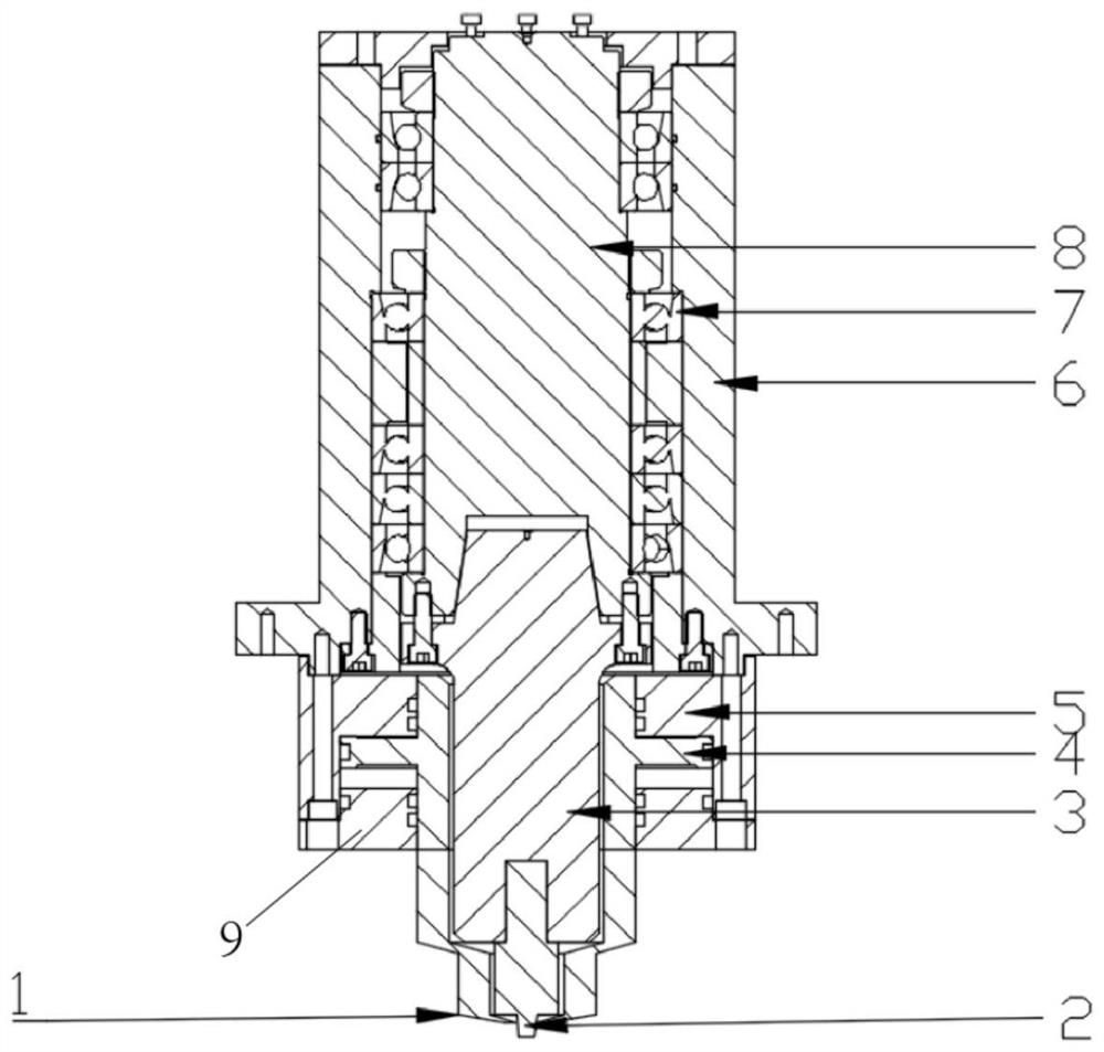
[0024] It can realize the static shoulder friction stir welding technology, and the closed-loop control of the shoulder and the stirring needle can control the spindle head device, including the clamping system, the hydraulic system and the static shoulder 1,

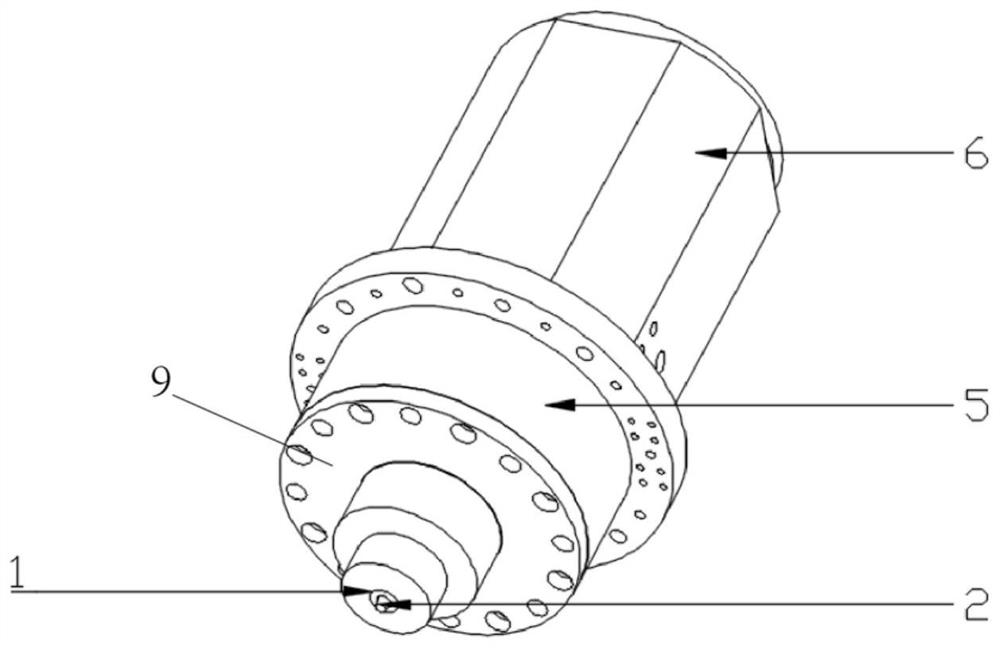
[0025] The clamping system includes a main shaft housing 6, a main shaft 8, a knife handle 3 and a stirring needle 2. The main shaft housing 6 adopts a hollow structure, and the main shaft 8 is arranged in the main shaft housing 6 through a bearing group 7. 3 is connected with the head end of the stirring needle 2;

[0026] The hydraulic system includes a piston rod 4 and an oil cylinder 5. The head end of the cylinder 5 is fixedly connected to the tail end of the main shaft housing 6. The piston rod 4 is arranged in the housing of the oil cylinder 5. The tail end of the piston rod 4 runs through the cylinder head 9 and the The head ends of the stationary shoulder 1 are connected, and the piston rod 4 can move up and do...

Embodiment 2

[0028] On the basis of Embodiment 1, the number of bearing groups 7 is 2 groups, and the bearing groups 7 are respectively arranged in groups along the main shaft 8 from top to bottom. The lower bearing set 7 has four bearings.

[0029] The bearing adopts angular contact bearing.

[0030] An outer spacer and an inner spacer are sequentially arranged between adjacent bearings from outside to inside.

[0031] A tight locking nut for fixing the bearing is arranged at the rear end of the bearing at the rearmost end.

Embodiment 3

[0033] On the basis of the second embodiment, the rear end of the stirring needle 2 is provided with a top wire hole for fixing the stirring needle 2 and the knife handle 3 , and the top wire passes through the top wire hole to connect the stirring needle 2 and the knife handle 3 .

[0034] The outer diameter of the stationary shoulder 1 is equal to the outer diameter of the piston rod 4, the inner diameter of the stationary shoulder 1 is greater than or equal to the maximum outer diameter of the stirring needle 2, and the stirring needle 2 runs through the stationary shoulder 1 and extends out of the stationary shoulder 1.


PUM


Abstract

The invention provides a spindle head device capable of realizing closed-loop control of a shoulder and a welding pin in a stationary shoulder friction stir welding technology. A spindle shell is of a hollow structure, a spindle is arranged in the spindle shell through a bearing pack, and the tail end of the spindle is connected with the head end of the welding pin through a cutter handle; and the head end of a shell of an oil cylinder is connected with the tail end of the spindle shell, a piston rod is arranged in the oil cylinder, the tail end of the piston rod penetrates through an oil cylinder cover to be connected with the head end of a static shoulder, and the piston rod can move up and down on the oil cylinder cover so as to achieve axial extending of the piston rod and further achieve the purpose of adjusting a distance between the static shoulder and a workpiece to be welded. The welding pin is separated from the stationary shoulder, the axial displacement of the welding pin can be adjusted in real time according to the requirements of a control system in a welding process, and closed-loop control over the axial displacement of the welding pin is achieved; and the device has the advantages of reasonable and flexible structural design and the like.

Description

technical field [0001] The invention relates to the technical field of friction stir welding, and more specifically relates to a spindle head device capable of realizing closed-loop control of a static shoulder friction stir welding technology shoulder and a stirring needle. Background technique [0002] Friction stir welding (FSW) technology is a solid-phase welding technology invented by the British Welding Institute. During the welding process, a high-speed rotating stirring head is inserted into the workpiece until the shoulder is in close contact with the surface of the workpiece, and thermal plastic is generated by friction between the shoulder and the surface of the workpiece. The weld metal is melted, and the stirring pin rotates and stirs to drive the weld metal to flow to form a solid-phase weld. Friction stir welding technology is widely used in the welding of light metal alloys such as aluminum alloys and magnesium alloys. [0003] Friction stir welding technolo...

Claims


Application Information

Patent Timeline
Patent Type & Authority Applications(China)
IPC IPC(8): B23K20/12
CPCB23K20/123B23K20/122
Inventor 王旭彤李京鹏刘伟
Owner 天津益普科技发展有限公司
Why Eureka
Try Eureka