Length-variable connecting rod device

A connecting rod device, a variable technology, applied in the direction of connecting rods, shafts and bearings, combustion engines, etc., can solve the problems of huge changes in production lines, failure to use engines, poor versatility, etc., achieve less processing procedures, improve switching responsiveness, The effect of reducing oil pressure

Active Publication Date: 2021-10-12
GUANGZHOU AUTOMOBILE GROUP CO LTD
View PDF18 Cites 0 Cited by
  • Summary
  • Abstract
  • Description
  • Claims
  • Application Information

AI Technical Summary

Problems solved by technology

[0003] However, there are still some shortcomings in the existing variable-length connecting rods. For example, the mechanism that needs to be implemented is very complicated, and the production line changes greatly; or the engine needs to be redesigned or significantly changed, which cannot be used on existing engines, and the versatility is poor.

Method used


Image

  • Length-variable connecting rod device
  • Length-variable connecting rod device
  • Length-variable connecting rod device

Examples


no. 1 example

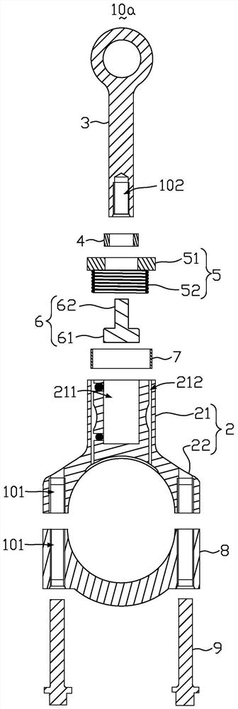
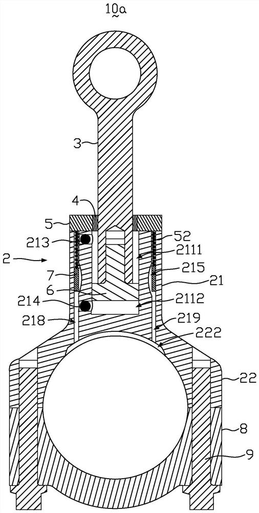
[0034] figure 1 It is an exploded view of the variable-length link device of the first embodiment of the present invention. figure 2 It is a structural schematic diagram of the length-variable link device according to the first embodiment of the present invention. Such as figure 1 with 2 As shown, the variable-length connecting rod device 10a includes a large-end connecting rod body 2, a small-end connecting rod body 3, a first sealing ring 4, a spring valve body 5, a transmission shaft 6, a second sealing ring 7, and a connecting rod cover 8 and connecting rod bolts 9. The transmission shaft 6 is movably arranged in the large end connecting rod body 2 , a part of the transmission shaft 6 is connected with the large end connecting rod body 2 , and the other part is connected with the small end connecting rod body 3 . The first sealing ring 4 is set on the spring valve body 5, the small end connecting rod body 3 passes through the first sealing ring 4 and is connected with...

no. 2 example

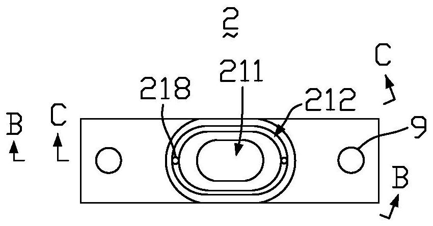
[0046] The structure of the variable-length connecting rod device 10b of the second embodiment of the present invention is the same as the structure of the variable-length connecting rod device 10a of the first embodiment, except that the oil chamber 211 and the first oil groove 212 of this embodiment are And the cross section of the transmission shaft 6 is circular. The working principle of the variable-length link device 10b of this embodiment is the same as the working principle of the variable-length link device 10a of the first embodiment, please refer to the description of the variable-length link device 10a of the first embodiment The working principle will not be elaborated here.

[0047]The variable-length connecting rod device 10a, 10b telescopic principle of the present invention consists of an oil chamber 211, a first oil groove 212, a first one-way valve 213, a second one-way valve 214, a second oil groove 215, a first oil passage 216, The second oil passage 217,...


PUM


Abstract

The invention discloses a length-variable connecting rod device. The length-variable connecting rod device comprises a large-head connecting rod body, the large-head connecting rod body comprises an oil cavity, a first oil groove, a first one-way valve, a second one-way valve, a second oil groove, a first oil way, a second oil way, a first oil inlet channel and a second oil inlet channel, and the first oil groove surrounds the oil cavity; the first one-way valve, the second one-way valve and the second oil groove are all arranged on the inner wall between the oil cavity and the first oil groove, the oil cavity is in communication with the first oil groove through the first one-way valve and the second one-way valve, the second oil groove is located between the first one-way valve and the second one-way valve and in communication with the first oil groove, one end of the first oil way is in communication with one end of the oil cavity, and the other end of the first oil way is in communication with the first oil groove; and one end of the second oil way is in communication with the other end of the oil cavity, the other end of the second oil way is in communication with the first oil groove, the first oil way and the second oil way are arranged in a crossed mode, the first oil inlet channel is in communication with one side of the first oil groove, and the second oil inlet channel is in communication with the other side of the first oil groove. The length-variable connecting rod device is simple in structure and high in compatibility.

Description

technical field [0001] The invention relates to the technical field of automobile manufacturing, in particular to a variable-length connecting rod device. Background technique [0002] Variable compression ratio technology is a revolutionary engine technology. Using high compression ratio at low load in the engine can improve engine thermal efficiency and reduce fuel consumption. Using low compression ratio at high load can increase engine power and torque to meet power requirements. At present, many OEMs and institutions have been researching the structure of parts and components of this technology for many years. Due to the large number of related structures and devices, if the variable compression ratio structure is complicated and the space requirement is large, then the entire engine needs to be greatly modified, and the technology is not yet available. The common purpose of different engines cannot be achieved; the variable compression ratio can be achieved by changing...

Claims


Application Information

Patent Timeline
IPC IPC(8): F16C7/04F16C7/06
CPCF16C7/04F16C7/06F16C2360/22Y02T10/12
Inventor 罗海鹏段心林占文锋吴广权徐昆朋
Owner GUANGZHOU AUTOMOBILE GROUP CO LTD
Why Eureka
Try Eureka