Light source system and projection display device

A technology of a light source system and a homogenizing device, which is applied in the field of projection display, can solve the problems of uneven projection display and difficult to achieve uniform mixing, and achieve the effect of improving uniformity and uniformity.

Pending Publication Date: 2021-10-12
APPOTRONICS CORP LTD
View PDF0 Cites 0 Cited by
  • Summary
  • Abstract
  • Description
  • Claims
  • Application Information

AI Technical Summary

Problems solved by technology

However, in the homogeneous mixing process of fluorescent light and laser light, it is often difficult to achieve a uniform mixing effect, resulting in inhomogeneity in the final projection display

Method used


Image

  • Light source system and projection display device
  • Light source system and projection display device
  • Light source system and projection display device

Examples


Embodiment 1

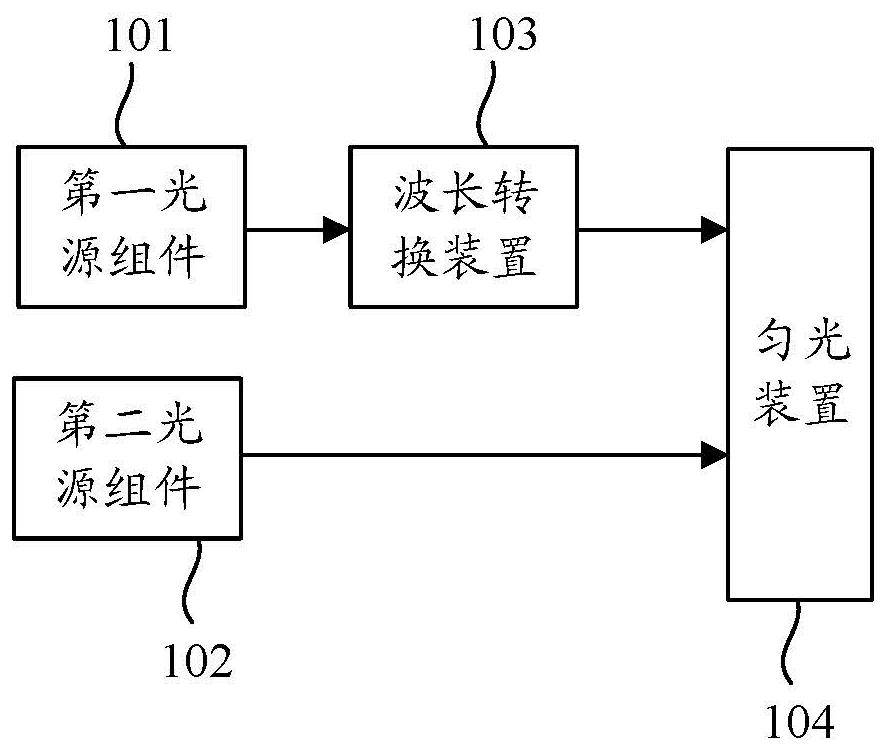
[0039] see image 3 , image 3 It is a schematic structural diagram of the first embodiment of the light source system provided in this application, and the light source system includes: a first light source assembly 101 , a second light source assembly 102 , a wavelength conversion device 103 and a light homogenization device 104 .

[0040] The first light source assembly 101 is used to emit at least two beams of excitation light, the first light source assembly 101 includes at least two first light emitters, each first light emitter is used to emit a beam of excitation light, and the color of the excitation light can be blue . The first light emitter may be a blue laser or a blue light emitting diode, and the number of lasers or light emitting diodes in the first light source component 101 may be selected according to needs. In other embodiments, the excitation light can also be ultraviolet light or light of other colors.

[0041] The second light source assembly 102 is u...

Embodiment 2

[0048] see Figure 4 , Figure 4 It is a schematic structural diagram of the second embodiment of the light source system provided in this application. In this embodiment, the first light source assembly includes a first laser 101a and a first laser 101b, the second light source assembly includes a second laser 102, and the second laser 102 is located between the first laser 101a and the first laser 101b, and the wavelength conversion device includes a wavelength conversion unit 103a and a wavelength conversion unit 103b. In this embodiment, the dodging component 104 is a square rod.

[0049] The excitation light emitted by the first laser 101a is laser light with a first wavelength distribution, the excitation light emitted by the first laser 101b is laser light with a third wavelength distribution, and the laser light emitted by the second laser 102 is laser light with a second wavelength distribution. Preferably, the first wavelength distribution and the third wavelength ...

Embodiment 3

[0056] see Figure 6 , Figure 6 is a schematic structural diagram of the third embodiment of the light source system provided by the application, and Figure 4 The difference of the illustrated embodiment is that the second light source assembly in this embodiment includes at least three second lasers, which are respectively the second laser 102a, the second laser 102b and the second laser 102c, wherein the second laser 102a, the first The laser 101a, the second laser 102c, the first laser 101b and the second laser 102b are arranged sequentially in the first direction or the second direction, that is, the first laser 101a is between the second laser 102a and the second laser 102c, the first The laser 101b is between the second laser 102c and the second laser 102b.

[0057] The light generated by the second laser 102a, the second laser 102b and the second laser 102c are respectively laser light having a second wavelength distribution, a fourth wavelength distribution and a s...


PUM


Abstract

The invention discloses a light source system and a projection display device. The light source system comprises a first light source assembly, a second light source assembly, a wavelength conversion device and a dodging device. The first light source assembly is used for emitting at least two beams of exciting light; the second light source assembly is used for emitting at least one laser beam; the wavelength conversion device is arranged on a light path of the at least two beams of exciting light and is used for converting the received at least two beams of exciting light into at least two beams of excited light; the dodging device is used for dodging the excited light and the laser; the excited light and the laser respectively form excited light spots and laser spots on the light incident side of the dodging device, the laser spots are located between two adjacent excited light spots, the two adjacent excited light spots are symmetrical about the laser spots, or the excited light spots are located between two adjacent laser spots, and the two adjacent laser spots are symmetrical about the excited light spots. Through the arrangement, the light emitting uniformity of the light source system can be improved, so that the projection display uniformity is improved.

Description

technical field [0001] The present application relates to the technical field of projection display, in particular to a light source system and a projection display device. Background technique [0002] With the continuous development of projection display technology, people have higher and higher requirements for the parameters of projection equipment. High brightness, HDR (High Dynamic Range, high dynamic range), high resolution and as large a color gamut as possible have become the current projectors. A very popular concept in the product market. Compared with bulb light source, LED (Light Emitting Diode, light emitting diode) light source and pure laser light source, projection equipment using laser fluorescent light source has the advantages of long life, high brightness and high cost performance, and it is an ideal choice for current projector light source. However, due to the wide spectral wavelength range of the fluorescence generated by laser excitation, there are ...

Claims


Application Information

Patent Timeline
Patent Type & Authority Applications(China)
IPC IPC(8): G03B21/20G02B27/10
CPCG03B21/2013G03B21/204G03B21/208G03B21/206G02B27/1006G02B27/10G03B21/20
Inventor 胡飞吴超李屹
Owner APPOTRONICS CORP LTD
Why Eureka
Try Eureka