Power supply distribution box for new energy bus and charging method

A technology of power distribution and new energy, which is applied in the direction of electric vehicle charging technology, charging stations, and electrical devices, etc., can solve problems such as battery power feeding, large safety hazards, and affecting normal operation of vehicles, so as to improve integration and save energy. Use cost, optimize the effect of vehicle power-off logic

Pending Publication Date: 2021-10-15
延边国泰新能源汽车有限公司
View PDF0 Cites 0 Cited by
  • Summary
  • Abstract
  • Description
  • Claims
  • Application Information

AI Technical Summary

Problems solved by technology

If the on-duty personnel are negligent or forget, it will cause the phenomenon of low-voltage battery feeding in the next morning, which will affect the normal operation of the vehicle and cause a great safety hazard

Method used


Image

  • Power supply distribution box for new energy bus and charging method
  • Power supply distribution box for new energy bus and charging method
  • Power supply distribution box for new energy bus and charging method

Examples


Embodiment 1

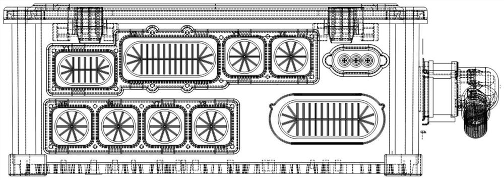
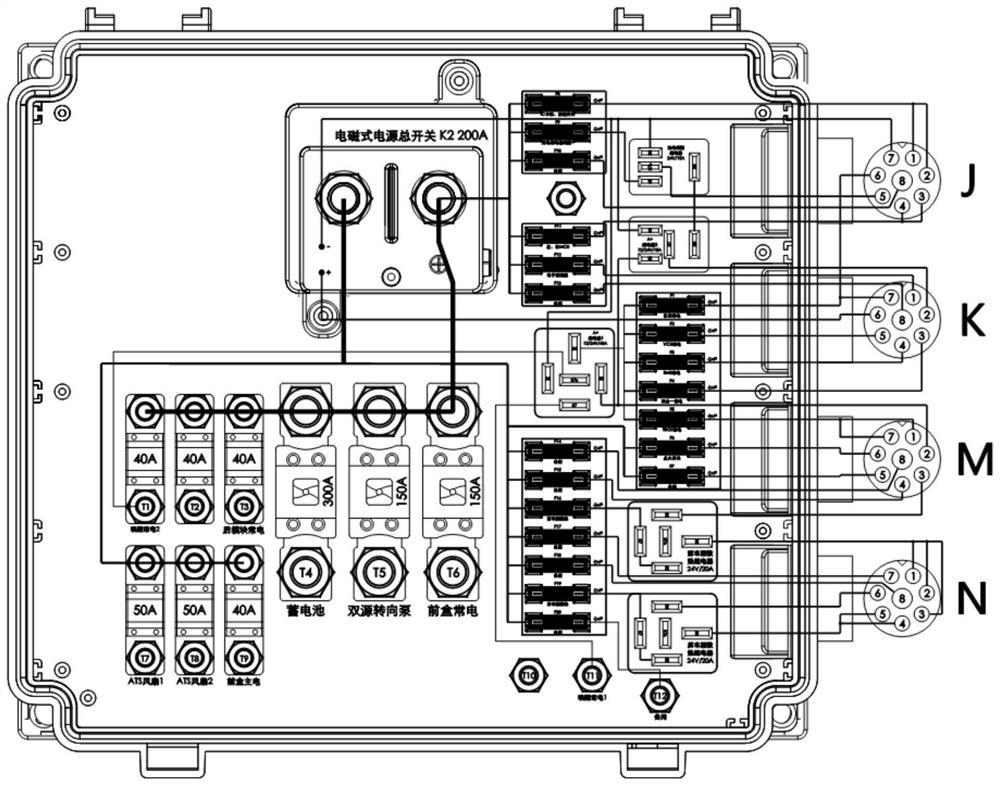
[0042] refer to figure 1 and figure 2 Shown: A power distribution box for new energy buses, including a housing and an outer cover arranged on the housing, and also includes 20-way chip fuses F1-F20 integrated inside the housing, 9-way flat-panel Insurance T1-T9, 5 relays are charging wake-up relay 1, first A+ relay 2 and second A+ relay 3 capable of receiving 12V power supply from charging pile, front compartment heat dissipation relay 4, rear compartment heat dissipation relay 5 and electromagnetic power supply Main switch 6;

[0043] refer to Figure 3 to Figure 5 As shown: the flat fuse T4 is connected to the flat fuse T1, T2, T3, T5, T6 respectively, the flat fuse T1 is connected to the normally closed contact of the first A+ relay 2, and the first A+ relay 2 is connected to the chip fuse respectively. F1-F5 connection, the chip insurance F1 is connected to the body instrument, the chip insurance F2 is connected to the body VCU, the chip insurance F3 is connected to t...

Embodiment 2

[0050] Electromagnetic power main switch delay power off

[0051] After the driver turns off the ignition switch, press the main switch of the electromagnetic power supply, the main switch of the electromagnetic power supply will give the rear module a switch value on the bottom side (with wake-up function, the wake-up is controlled by the "ON" signal of the ignition switch to enter the working state ), the module will delay for 5 seconds to cut off the control line of the main switch of the electromagnetic power supply to reserve time for the storage of the vehicle system.

Embodiment 3

[0053] The main switch of the mechanical power supply is disconnected (see Figure 5 )

[0054] 1) When charging

[0055] The charging pile is connected to the high-voltage power battery 8, and at the same time, there will be a 12V power supply to the first A+ relay 2 and the second A+ relay 3, and the normally open contacts "30, 87" of the two relays are closed, thereby stimulating the low-voltage battery 7 to work ;

[0056] The source of the wake-up power supply: the current of the low-voltage battery 7 flows into the second A+ relay 3 after being insured at 5A. Since the normally open contact "30, 87" of the second A+ relay 3 is closed, the current continues to be charged to wake up the normally closed contact of the relay 1. At point "30, 87a", since the mechanical power switch 9 is in the off state, the normally closed contact "30, 87a" of the charging wake-up relay 1 is still in the closed state, so the charging wake-up relay 1 can supply current to the VCU , instrum...


PUM


Abstract

The invention provides a power distribution box for a new energy bus and a charging method, and the power distribution box comprises a housing and an outer cover disposed on the housing, and comprises 20 chip type fuses F1-F20 and the 9 flat plate type fuses T1-T9 that are integrated in the shell, 5 relays are a charging wake-up relay, a first A + relay and a second A + relay which can receive 12V power supply from a charging pile, and the front compartment heat dissipation relay, the rear compartment heat dissipation relay and the electromagnetic power supply main switch are arranged in the shell. The power distribution box provided by the invention is compact in structure, optimizes the power-off logic of the whole vehicle, realizes the charging when the whole vehicle is powered off, and avoids the situation that the low-voltage storage battery cannot normally operate next day due to the feed fault, and the feed also means that the electric equipment of the whole vehicle continues to consume the electric quantity of the storage battery after the charging is finished. The mechanical power supply main switch can be turned off to charge the whole vehicle, a specially-assigned person is not needed after charging is finished, the charging safety is improved, and the use cost of an operation unit is saved.

Description

technical field [0001] The invention belongs to the technical field of new energy buses, and in particular relates to a power distribution box and a charging method for new energy buses. Background technique [0002] With the vigorous development of my country's industrial civilization, the problem of environmental pollution is becoming more and more serious, and new energy vehicles use non-traditional energy to power vehicles, which greatly reduces the impact of vehicle emissions on the environment, such as electric vehicles, hydrogen Such energy vehicles can even achieve true zero emissions. [0003] In order to comply with the development trend of new energy vehicles, with the continuous advancement of science and technology, new energy buses will also develop towards a highly intelligent and integrated direction. Due to the replacement of the energy source of the bus, the following problems are highlighted in the new energy bus: 1) The number of electrical components is ...

Claims


Application Information

Patent Timeline
Patent Type & Authority Applications(China)
IPC IPC(8): B60L53/22B60L53/14B60L3/00B60R16/023
CPCB60L53/22B60L53/14B60L3/00B60R16/0239B60R16/0238Y02T10/70Y02T10/7072Y02T90/14
Inventor 李博冉家续张帅战文博
Owner 延边国泰新能源汽车有限公司
Why Eureka
Try Eureka