
Thin-gauge non-oriented silicon steel 35BW440 and production method thereof

A technology of oriented silicon steel and production method, which is applied in the field of alloy smelting, can solve problems such as normalization annealing, and achieve the effect of improving surface quality and improving electromagnetic properties

Inactive Publication Date: 2021-10-15
BENGANG STEEL PLATES
View PDF8 Cites 3 Cited by
  • Summary
  • Abstract
  • Description
  • Claims
  • Application Information

AI Technical Summary

Problems solved by technology

[0003] In the prior art, it is usually necessary to use argon gas sealing and electromagnetic stirring during continuous casting to increase the magnetic induction of non-oriented silicon steel. Finally, it is necessary to normalize the hot-rolled coil. The function of normalized annealing is to improve the crystal Granular structure, but there is no electromagnetic stirring equipment and normalizing annealing equipment on the production line of some steel mills

Method used


Image

  • Thin-gauge non-oriented silicon steel 35BW440 and production method thereof
  • Thin-gauge non-oriented silicon steel 35BW440 and production method thereof
  • Thin-gauge non-oriented silicon steel 35BW440 and production method thereof

Examples


Embodiment 1

[0035] This embodiment provides a thin non-oriented silicon steel 35BW440, the non-oriented silicon steel 35BW440 includes the following elements by mass percentage:

[0036] C: ≤0.003%, Si: 0.8%-2.0%, Mn: 0.4%-1.2%, P: ≤0.015%, S: ≤0.003%, Als: 0.25%-0.6%, N: ≤0.003%, Sb: 0.04%-0.1%, O: ≤0.0025%, the rest is Fe and unavoidable impurities.

[0037] On the premise that there is no electromagnetic stirring equipment to increase the magnetic induction intensity of non-oriented silicon steel, by adding Sb elements, the {110} and {100} texture components that are beneficial to electromagnetic properties are added to improve electromagnetic properties. Specifically, Sb elements are in the grain boundary Nearby segregation improves the formation of {100} and {110} texture components that are beneficial to electromagnetic properties, improves the magnetic induction of non-oriented silicon steel, and reduces the iron loss value.

[0038] Furthermore, by adding Sb element, the electrom...

Embodiment 2

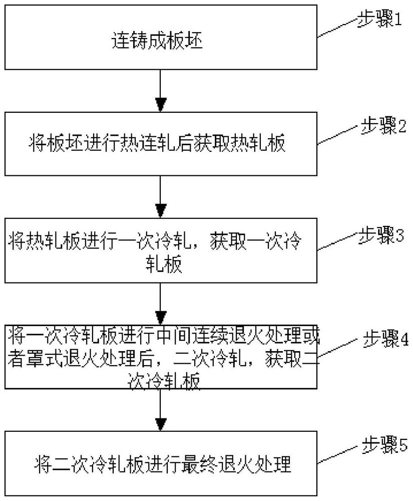
[0043] figure 1 A schematic flow chart showing a method for producing thin-gauge non-oriented silicon steel 35BW440 according to an embodiment of the present invention is shown.

[0044] like figure 1 As shown, the present embodiment provides a production method of thin-gauge non-oriented silicon steel 35BW440, the production method comprising the following steps:

[0045] Step 1, continuous casting into a slab;

[0046] Step 2, hot-rolling the slab to obtain a hot-rolled plate;

[0047] Step 3, performing a cold rolling on the hot-rolled plate to obtain a cold-rolled plate;

[0048] Step 4, performing intermediate continuous annealing or bell annealing on the primary cold-rolled sheet, and performing secondary cold-rolling to obtain a secondary cold-rolled sheet;

[0049] In step 5, the secondary cold-rolled sheet is subjected to final annealing treatment.

[0050] It should be noted that after obtaining the hot-rolled sheet, it is necessary to perform normalization trea...


PUM

PropertyMeasurementUnit
Iron lossaaaaaaaaaa
Magnetic senseaaaaaaaaaa
Tensile strengthaaaaaaaaaa

Abstract

The invention relates to thin-gauge non-oriented silicon steel 35BW440. The non-oriented silicon steel 35BW440 comprises the following elements including, by mass, less than or equal to 0.003% of C, 0.8%-2.0% of Si, 0.4%-1.2% of Mn, less than or equal to 0.015% of P, less than or equal to 0.003% of S, 0.25%-0.6% of Als, less than or equal to 0.003% of N, 0.04%-0.1% of Sb, less than or equal to 0.0025% of O and the balance Fe and inevitable impurities. On the premise that no electromagnetic stirring equipment is used for increasing the magnetic induction intensity of the non-oriented silicon steel, the electromagnetic performance is improved by adding the Sb element and increasing {110} and {100} texture components beneficial to the electromagnetic performance, and the surface quality of the non-oriented silicon steel is improved by adopting the processes of secondary cold rolling and intermediate continuous annealing.

Description

technical field [0001] The invention relates to the technical field of alloy smelting, in particular to a thin gauge non-oriented silicon steel 35BW440 and a production method thereof. Background technique [0002] Non-oriented silicon steel is a ferrosilicon alloy with very low carbon content. In the steel plate after deformation and annealing, its grains are distributed in random orientation. The product is usually a cold-rolled plate or strip with a nominal thickness of 0.35 and 0.5mm. For the manufacture of motors and generators, the magnetic induction of non-oriented silicon steel is high, and silicon steel sheets with higher magnetic induction can be obtained under the same magnetic field. The volume and weight of the motor or transformer core made with it are relatively small, which can save Silicon steel sheets, copper wires and insulating materials, etc. [0003] In the prior art, it is usually necessary to use argon gas sealing and electromagnetic stirring during ...

Claims


Application Information

Patent Timeline
IPC IPC(8): C22C38/02C22C38/04C22C38/06C22C38/60C21D1/26C21D6/00C21D8/12
CPCC22C38/004C22C38/02C22C38/04C22C38/06C22C38/60C21D1/26C21D6/005C21D6/008C21D8/1216C21D8/1244
Inventor 李毅伟李德君王溪刚乔浩浩
Owner BENGANG STEEL PLATES
Learn More