Upper deslagging system on full-section vertical shaft heading machine

A roadheader and full-section technology, applied in shaft equipment, sinking, mining equipment, etc., can solve the problems of large space occupied by motors, pump bodies and pipelines, low efficiency of slag discharge, limited space, etc., and shorten continuous conveying Length, reduce pump suction pressure, increase the effect of slag discharge capacity

Pending Publication Date: 2021-10-15
CHINA RAILWAY 15TH CONSTR BUREAU GRP
View PDF6 Cites 1 Cited by
  • Summary
  • Abstract
  • Description
  • Claims
  • Application Information

AI Technical Summary

Problems solved by technology

[0003] At present, the existing shaft boring machines generally use mechanical discontinuous slagging such as hopper or fluid suction slagging when discharging slag. The slagging efficiency of mechanical discontinuous slagging is low, and the suction slagging is more efficient. The slurry is directly discharged from the shaft. For deep shafts > 50 meters, especially ultra-deep shafts > 100 meters, the space in the shaft is limited. If the slurry is discharged together, the motor power and the suction pressure and power of the mud pump will be affected. There are extremely high requirements for use, and correspondingly the motors, pump bodies and pipelines used also occupy a relatively large space. The limitation of space makes the slag discharge capacity of the existing upper slag discharge system limited. With the continuous progress of excavation, the discharge The slag distance keeps increasing, but the slag production rate remains basically unchanged, so that the slag discharge capacity cannot match the tunneling capacity of the shaft boring machine, which in turn affects the tunneling efficiency of the shaft boring machine

Method used


Image

  • Upper deslagging system on full-section vertical shaft heading machine
  • Upper deslagging system on full-section vertical shaft heading machine
  • Upper deslagging system on full-section vertical shaft heading machine

Examples


Embodiment 1

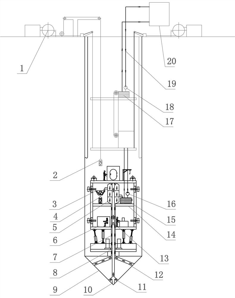
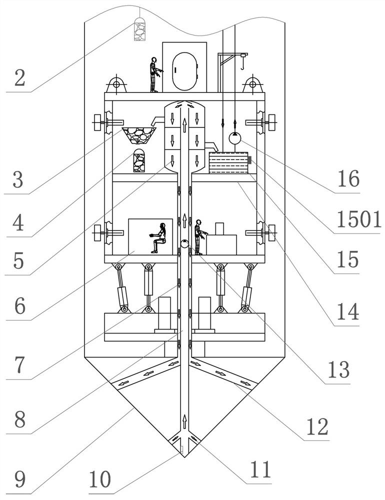
[0029] Such as Figure 1 to Figure 4 As shown, the slag discharge system on the full-face shaft boring machine of this embodiment includes a cutter head 9, and the cutter head 9 is provided with a jet port 12 for spraying liquids such as clear water or mud to the shaft section when the cutter head 9 is tunneling, and a The slag suction port 11 and the center of the cutter head 9 are provided with a multi-layer casing type center column at the center of the slag suction port 11 for absorbing the slurry produced at the shaft section, and the multi-layer casing type center column includes a slag suction pipe 8 communicated with the slag suction port 11 and The jet pipe 7 is sleeved outside the slag suction pipe 8 and communicated with the jet port 12 for providing flushing liquid to the jet port 12, and a ring shape is formed between the jet pipe 7 and the slag suction pipe 8 for the flushing liquid to flow therein. aisle.

[0030] The upper slag discharge system of this embodim...

Embodiment 2

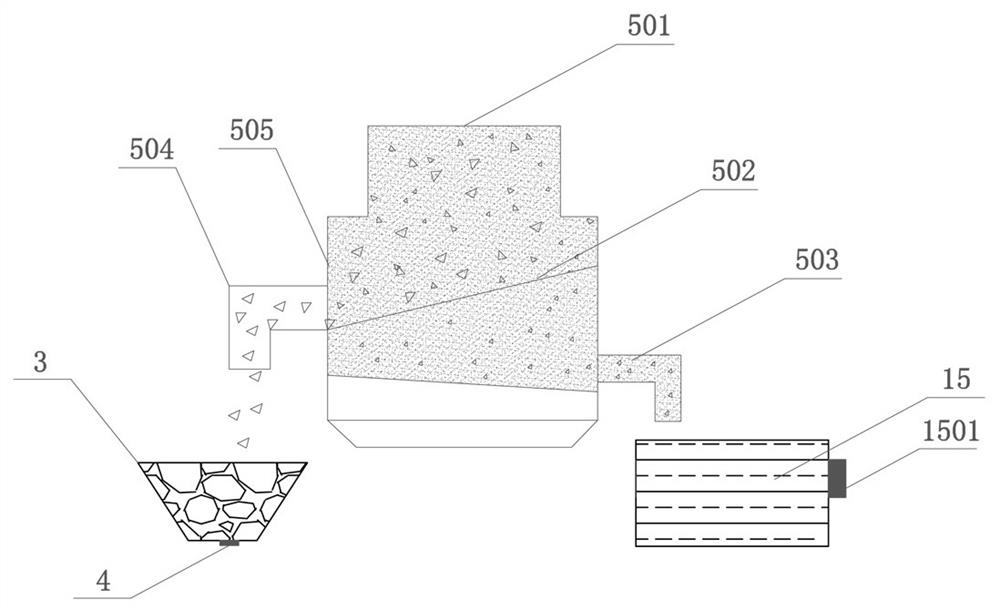
[0038] The slag discharge system on the full-face shaft boring machine of this embodiment is different from that of Embodiment 1 in that the solid storage bin 3 can be fixed on the relay platform 14 during implementation, and the bottom of the solid storage bin 3 is provided for detecting solids. The gravity sensor 4 of the weight of the storage bin 3, when the rock slag enters the solid storage bin 3, the signal of the gravity sensor 4 can feed back the amount of the rock slag accumulated in the solid storage bin 3, in the liquid storage bin 15 There is a liquid level gauge 1501 for detecting the height of the slurry in the liquid storage bin 15. By setting the gravity sensor and the liquid level gauge 1501, when the rock slag in the solid storage bin 3 reaches the set weight, start the winch 1 to lift the bucket 2 Put it down and hang out the rock slag in the solid storage bin 3. When the liquid level gauge 1501 reaches the set liquid level, you can turn on the slurry pump 16...


PUM


Abstract

The invention provides an upper deslagging system on a full-section vertical shaft heading machine. The upper deslagging system comprises a cutter head provided with a slag suction opening and a jet flow opening, and a multi-layer sleeve type center column arranged in the center of the cutter head; the multi-layer sleeve type center column comprises a slag suction pipe communicating with the slag suction opening and a jet flow pipe arranged outside the slag suction pipe in a sleeving mode and communicating with the jet flow opening; the upper deslagging system further comprises a relay platform; a solid-liquid separation device communicating with the slag suction pipe is arranged on the relay platform; a slurry pump is arranged on the slag suction pipe; the solid-liquid separation device is provided with a solid storage bin and a liquid storage bin; the upper deslagging system further comprises a hoisting bucket and a liquid discharging pipe which communicates with the liquid storage bin and is used for extending out of a vertical shaft; a winch is connected with the hoisting bucket; and the slurry pump is arranged on the liquid discharging pipe. By arranging the relay platform with the solid-liquid separation device, slag slurry at a tunneling section is sucked into the relay platform for separation of rock slag from the slurry when the cutter head of the heading machine breaks rock, and then the rock slag and the slurry are respectively discharged, so that the slag discharging capability of the upper deslagging system can be obviously improved.

Description

technical field [0001] The invention relates to the technical field of shaft construction, in particular to a slag discharging system on a full-section shaft boring machine. Background technique [0002] The shaft is the main channel for underground mineral mining, long tunnel ventilation and other underground projects. In the process of shaft construction, rock slag will be continuously produced at the excavation section when the cutterhead of the roadheader breaks the rock. One of the difficulties in shaft construction is how to discharge slag vertically and efficiently. [0003] At present, the existing shaft boring machines generally use mechanical discontinuous slagging such as hopper or fluid suction slagging when discharging slag. The slagging efficiency of mechanical discontinuous slagging is low, and the suction slagging is more efficient. The slurry is directly discharged from the shaft. For deep shafts > 50 meters, especially ultra-deep shafts > 100 meters,...

Claims


Application Information

Patent Timeline
Patent Type & Authority Applications(China)
IPC IPC(8): E21D1/06E21D1/00E21F17/00E21F17/18
CPCE21D1/06E21D1/00E21F17/00E21F17/18
Inventor 黄昌富李阁强刘中欣张庆军肖清安宗志栓焦雷吴康王帅袁畅邱泽刚李凌霄董振乐李东林
Owner CHINA RAILWAY 15TH CONSTR BUREAU GRP
Why Eureka
Try Eureka