Resonance suppression method, module and device of converter

A resonance suppression and converter technology, applied in the field of control, can solve problems such as limited resonance damping capacity, achieve the effects of avoiding the limitation of resonance damping capacity, reducing resonance risk, and enhancing stable operation capability

Pending Publication Date: 2021-10-15
SHENZHEN HOPEWIND ELECTRIC CO LTD
View PDF5 Cites 0 Cited by
  • Summary
  • Abstract
  • Description
  • Claims
  • Application Information

AI Technical Summary

Problems solved by technology

[0011] In view of this, the purpose of this application is to provide a converter resonance suppression method, module and device to solve the problem that the resonance suppression strategy of the grid-connected converter is limited due to the delay of the digital control system.

Method used


Image

  • Resonance suppression method, module and device of converter
  • Resonance suppression method, module and device of converter
  • Resonance suppression method, module and device of converter

Examples


Embodiment 1

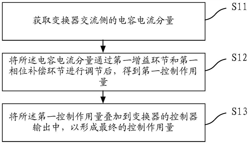
[0054] Such as figure 1 As shown, Embodiment 1 of the present application provides a method for suppressing resonance of a converter, the method comprising:

[0055] Step S11, obtaining the capacitive current component of the AC side of the converter;

[0056] Step S12, after adjusting the capacitive current component through the first gain link and the first phase compensation link, the first control action amount is obtained;

[0057] Step S13, adding the first control action to the controller output of the converter to form a final control action.

[0058] In this example, the first gain link includes a pure proportional link and / or a functional module with filtering characteristics. The transfer function of the input and output characteristics of the first phase compensation link includes a FIR filter function.

[0059] In this way, by introducing a phase compensator with an input-output characteristic transfer function including an FIR filter function in the capacitive...

Embodiment 2

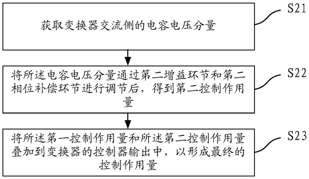
[0066] Such as figure 2 As shown, different from Embodiment 1, the method also includes:

[0067] Step S21, obtaining the capacitive voltage component on the AC side of the converter;

[0068] Step S22, after adjusting the capacitor voltage component through the second gain link and the second phase compensation link, a second control action is obtained;

[0069] Step S23, adding the first control action amount and the second control action amount to the controller output of the converter to form a final control action amount.

[0070] It should be noted that the steps of obtaining the first control action (S11 and S12) and the steps of obtaining the second control action (S21 and S22) can be performed in no order, for example: the first control action can be obtained first, Then get the second control action; you can also get the second control action first, and then get the first control action; or get the two action at the same time.

[0071] In this example, the second...

Embodiment 3

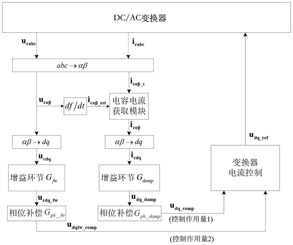
[0074] image 3 It is a schematic diagram of the resonance suppression implementation process of the converter in the third embodiment of the present application.

[0075] The control action 1 can be obtained through the following steps: First, obtain the dq component i of the capacitive current on the AC side of the converter cdq , then the component i cdq Through the gain link G damp and phase compensation link G ph_damp , you can get it. Specifically, the component i cdq Through the gain link G damp Then get the initial control action u dq_damp , u dq_damp Then through the phase compensation link G ph_damp after getting u dq_comp , u dq_comp That is, the control action 1. G damp It can be a pure proportional link, or a module with filtering function, or a combination of both.

[0076] Among them, the dq component i of the capacitive current on the AC side of the converter cdq It can be obtained by:

[0077] Method 1: For the vector u of the capacitor voltage ...


PUM


Abstract

The invention discloses a resonance suppression method, module and device of a converter. The method comprises the following steps: acquiring a capacitive current component of an alternating current side of the converter; after the capacitance current component is adjusted through a first gain link and a first phase compensation link, obtaining a first control action quantity; and superimposing the first control action into a controller output of the converter to form a final control action. According to the invention, the phase compensator is introduced into the capacitor current feed-forward control branch, the problem that the resonance damping capability is limited due to the delay of a digital control system in the existing resonance suppression method is avoided on the basis of not increasing the system cost, the resonance risk of the converter operating under wide-range power grid impedance is reduced, and the stable operation capability under power grids with different intensities is enhanced.

Description

technical field [0001] The present application relates to the field of control technology, in particular to a method, module and device for suppressing resonance of a converter. Background technique [0002] In order to filter out high-frequency harmonics, grid-connected converters are often equipped with high-order filters at the AC input or output, and the widely used LCL filter is one of them. Under the same filtering performance requirements, the use of high-order filters can not only reduce the volume of the filter, save system cost, but also help to increase the power density of the system. However, the output characteristics of high-order filters also bring resonance risks to the converter. [0003] The resonance suppression strategy based on software control is currently the mainstream method for converters to deal with resonance. Among them, the resonance suppression strategy based on capacitive current feedforward is the most widely used and studied. Due to the ...

Claims


Application Information

Patent Timeline
Patent Type & Authority Applications(China)
IPC IPC(8): H02J3/01H02J3/38H02M1/12H02M7/5387H02M1/08
CPCH02J3/01H02J3/381H02M1/12H02M7/53873H02M1/08Y02E40/40
Inventor 周党生陈佳明
Owner SHENZHEN HOPEWIND ELECTRIC CO LTD
Why Eureka
Try Eureka