Mechanical arm control method and device, mechanical arm and readable storage medium

A control method and a technology of a mechanical arm, applied in the field of mechanical arms and readable storage media, devices, and control methods of a mechanical arm, can solve problems such as different forces, force control, and inability to move the position of the mechanical arm, and achieve a small amount of calculation and improved speed effect

Active Publication Date: 2021-10-19
UBTECH ROBOTICS CORP LTD
View PDF8 Cites 2 Cited by
  • Summary
  • Abstract
  • Description
  • Claims
  • Application Information

AI Technical Summary

Problems solved by technology

However, because the processing, assembly, electrical components, etc. are different from the theory, the actual quality parameters are different from the CAD model, and the manipulators installed at the end of many mechanical arms cannot use the CAD model to obtain their theoretical model parameters
As a result, the control end of the robotic arm cannot accurately obtain the mass and center of mass of the manipulator, which affects the inability of the control end of the robotic arm to perform precise position movement and force control on the robotic arm

Method used


Image

  • Mechanical arm control method and device, mechanical arm and readable storage medium
  • Mechanical arm control method and device, mechanical arm and readable storage medium
  • Mechanical arm control method and device, mechanical arm and readable storage medium

Examples


Embodiment 1

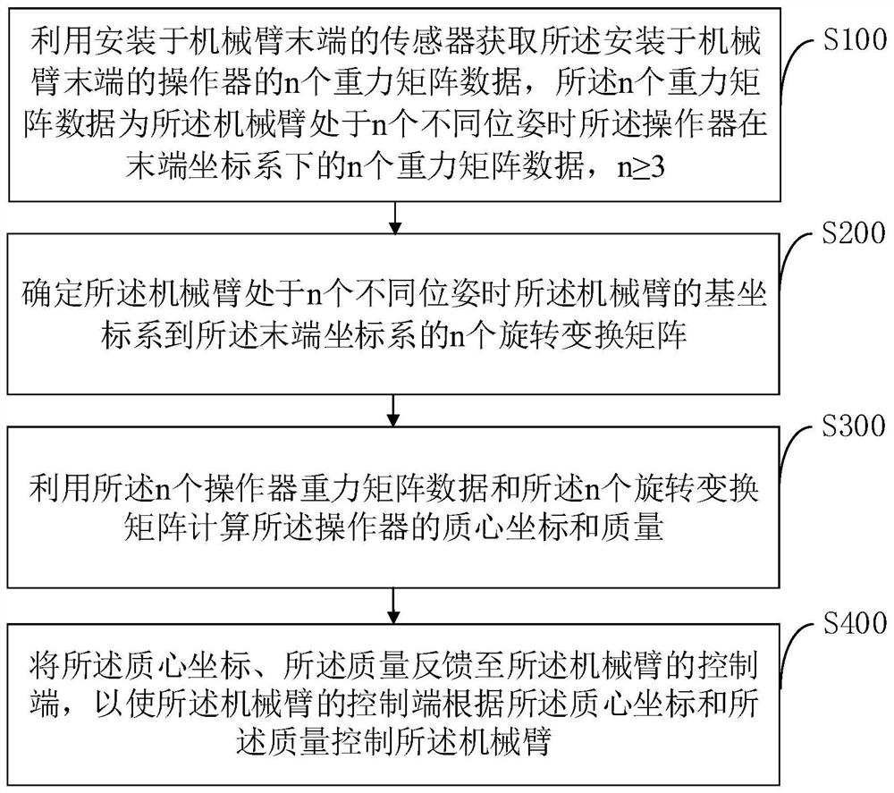
[0054] An embodiment of the present application proposes a method for controlling a mechanical arm, such as figure 1 As shown, the mechanical arm control method includes the following steps:

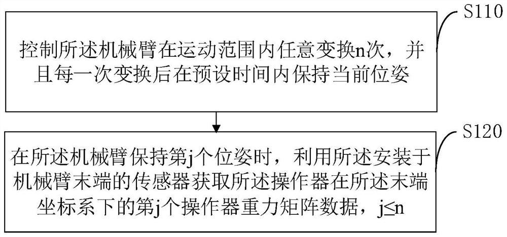
[0055] S100: Obtain n pieces of gravity matrix data of the manipulator installed at the end of the robot arm by using a sensor installed at the end of the robot arm, the n pieces of gravity matrix data are the operations when the robot arm is in n different poses n gravity matrix data of the device in the end coordinate system, n≥3.

[0056] Since the contact between the manipulator and the working surface is often an unknown complex surface, when determining the gravity of the manipulator at the end coordinate system of the manipulator at the end of the manipulator, it is necessary to use a six-dimensional force sensor to obtain n different positions of the manipulator. The n gravity matrix data of the manipulator at the end of the manipulator in the end coordinate system during the po...

Embodiment 2

[0091] Further, the center of mass coordinates and quality of the manipulator are determined using the following formula:

[0092]

[0093] in, j=1, 2 or 3, m represents the quality of the operator, r c represents the coordinates of the center of mass of the manipulator, f FTbias Indicates the static error of the force collected by the sensor at the end of the manipulator, τ FTbias Indicates the static error of the torque collected by the sensor at the end of the manipulator, Y j Indicates the parameter matrix corresponding to the jth pose, Represents the transpose matrix corresponding to the jth rotation transformation matrix, g represents the gravitational acceleration vector, express request The antisymmetric matrix of , 0 1×3 Represents a zero matrix with 1 row and 3 columns, I 3×3 Represents an identity matrix with 3 rows and 3 columns, 0 3×3 Represents a zero matrix with 3 rows and 3 columns, W j Indicates the gravity matrix data corresponding to the jth ...

Embodiment 3

[0104] Further, see Figure 5 , the mechanical arm control method also includes the following steps:

[0105] S500: Feedback the static error of the sensor installed at the end of the mechanical arm to the control end of the mechanical arm.

[0106] Feedback the static error of the sensor installed at the end of the manipulator to the control end of the manipulator, so that the control end can analyze the direction of gravity and the static error according to the center of mass coordinates and mass of the manipulator and the static error of the sensor at the end of the manipulator Compensation, and then issue accurate control instructions, improve control accuracy, and improve the dynamic and steady-state performance of the robotic arm.


PUM


Abstract

The invention discloses a mechanical arm control method and device, a mechanical arm and a readable storage medium. The method comprises the steps that n pieces of gravity matrix data of an operator at the tail end of the mechanical arm under a tail end coordinate system when the mechanical arm is in n different poses are obtained through a sensor at the tail end of the mechanical arm, and n is larger than or equal to 3; n rotation transformation matrices from a base coordinate system of the mechanical arm to the tail end coordinate system are determined by using a preset rotation transformation matrix determination method when the mechanical arm is in n different poses; and a center-of-mass coordinate and the mass of the operator can be calculated only by acquiring the n pieces of gravity matrix data and the n pieces of rotation transformation matrices corresponding to the n different poses of the mechanical arm. According to the technical scheme, the power-on error of a force sensor is fully considered, the calculated amount is small, on-line data processing can be achieved, the center-of-mass coordinate and the mass of the operator can be determined, model parameters do not need to be modified after off-line solving, and the speed of determining the related parameters of the operator is effectively increased.

Description

technical field [0001] The present invention relates to the technical field of mechanical arm applications, and in particular to a control method and device for a mechanical arm, a mechanical arm and a readable storage medium. Background technique [0002] With the promotion and popularization of robotic arms in the field of service robots, robotic arms are usually used instead of robotic arms to perform different tasks, and for different tasks, different manipulators are installed at the end of the robotic arm to grab or hold loads , For example, a suction cup manipulator can be used when grabbing boxes, a multi-finger gripper can be used when grabbing irregular objects, and corresponding pen clips can be installed when writing. Manipulators with different mass properties will affect the position and force control of the manipulator. [0003] In the prior art, relevant mass and centroid parameters can be obtained through the CAD model of the manipulator. However, due to d...

Claims


Application Information

Patent Timeline
Patent Type & Authority Applications(China)
IPC IPC(8): B25J9/16B25J13/08B25J18/00
CPCB25J9/1679B25J9/1602B25J9/1656B25J13/085B25J18/00
Inventor 黄荔群任晓雨赵明国熊友军
Owner UBTECH ROBOTICS CORP LTD
Why Eureka
Try Eureka