Intelligent dyeing system and method

A dyeing system and intelligent technology, applied in the field of intelligent dyeing system, can solve the problems of misdiagnosis and missed diagnosis, low inspection efficiency, unfavorable smear and other problems

Inactive Publication Date: 2021-10-19
重庆德方信息技术有限公司
View PDF0 Cites 1 Cited by
  • Summary
  • Abstract
  • Description
  • Claims
  • Application Information

AI Technical Summary

Problems solved by technology

[0003] At present, the above operations are mainly performed manually by the staff. Different operators have different control over the amount of dyeing solution, the dyeing time, and the degree of dyeing uniformity of the dyeing solution. Observation and analysis under the cell microscope have a great influence on the judgment. Not only is the quality of observation difficult to guarantee, the staff also need to spend a lot of time looking for cells that meet the observation requirements in

Method used


Image

  • Intelligent dyeing system and method

Examples


Embodiment 1

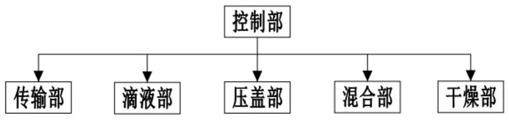
[0039] like figure 1 As shown, the intelligent dyeing system includes a transport unit, a dropping portion, a mixing portion, a compression cap portion, a drying portion, and a control portion.

[0040] The transfer unit includes a motion transport mechanism, a first robust arm, and a sensor for automatically putting the smear in a staining region and stained out the dyeing area.

[0041] Specifically, the smear to be stained is placed on the smear transmission rail, and the transport mechanism employs a stepper motor to move the synchronous wheel, the synchronous belt, and the guide rail fixing the rail slider fixed on the synchronization belt, and fixed in the guide rail slider. The push block pushes the smear movement of the smear transport guide along the barrier of the guide rail, the control unit controls the direction of rotation and the number of steps of the stepper motor to implement the smear from the initial placement position to a predetermined dyeing area.

[0042] T...

Embodiment 2

[0058] Unlike the embodiment, in the present embodiment, the image capture portion is further included for collecting the dye image of the smear, and transmitted to the control unit;

[0059] In this embodiment, the mixing portion is a blowing mechanism, specifically a fan;

[0060] The transport unit also includes a placement, a placement seat is fixed to the transport mechanism, and the placement seat includes a downward base, a tilt mechanism, and a placed seat; the base is fixed, the fixing mechanism includes four respective and control units. The electrode rod is fixed to the base, and the free end of the electrode rod is fixed to the bottom surface of the platen seat;

[0061] After the control unit is further configured to discharge the dyeing liquid to the dyeing liquid, the control unit analyzes the position and uniformity of the dyeing image. If the analysis result is the position or uniformity does not reach the preset standard, the control unit generates the coating Hy...


PUM


Abstract

The invention belongs to the technical field of cell observation, and particularly relates to an intelligent dyeing system and method. The system comprises a transmission part which comprises a motion transmission mechanism, a first mechanical arm and a sensor and is used for automatically putting a smear into a dyeing area and taking the smear out of the dyeing area after dyeing, a liquid dripping part which comprises a second mechanical arm, a dyeing liquid dripping pipeline, a cleaning liquid flushing pipeline and a waste liquid collecting pipeline, and is used for dripping dyeing liquid and buffer liquid to the smear and flushing redundant dyeing liquid after dyeing, a mixing part which is used for uniformly mixing the dyeing liquid and the buffer liquid on the smear, a gland part which is used for fixing and sealing the smear, a drying part which is used for drying the smear which is dyed and washed, and a control part which is used for controlling the transmission part, the liquid dripping part, the mixing part, the gland part and the drying part according to preset operation steps. The observation liquid prepared by using the system not only has a better observation effect, but also enables the observation to be more efficient.

Description

Technical field [0001] The present invention belongs to the field of cell smear staining, and more particularly to an intelligent dyeing system and method. Background technique [0002] In order to effectively observe the cells and tissues, it is necessary to treat it before observation with a microscope. Specifically, it is necessary to apply the specimen to the slide to form a single layer uniform coating (referred to as a smear, such as blood, bone marrow, etc.), and the smear is fixed and dried using a special process, and then the dyeing liquid And the buffer is dropped in the smear, the buffer is sufficiently contacted with the coating (the nucleus and cytoplasm are dyed into different colors). After dyeing, the cleaning liquid is flushed with the cleaning liquid to rinse the excess liquid. Ohasia, then dried the flushing smear. The dyeing smear was then placed on the microscope for cell detection. [0003] At present, the above operation is mainly manually operated by the ...

Claims


Application Information

Patent Timeline
IPC IPC(8): G01N1/30G01N1/31
CPCG01N1/30G01N1/31
Inventor 李春林
Owner 重庆德方信息技术有限公司
Why Eureka
Try Eureka